Showing posts with label doffer. Show all posts

Wednesday, September 14, 2022

कार्डिंग प्रक्रिया, कार्डिंग के उद्देश्य, कार्डिंग मशीन की संरचना, कार्डिंग मशीन की कार्य प्रक्रिया (CARDING PROCESS, OBJECTIVES OF CARDING, STRUCTURE OF CARDING MACHINE, WORKING PROCEDURE OF CARDING MACHINE)

 कार्डिंग प्रक्रिया, कार्डिंग के उद्देश्य, कार्डिंग मशीन की संरचना, कार्डिंग मशीन की कार्य प्रक्रिया


कार्डिंग प्रक्रिया :

कार्डिंग कताई की दूसरी प्रक्रिया होती  है जो फीड सामग्री (लैप ) को "स्लाइवर" ( फाइबर के एक समान स्ट्रैंड में परिवर्तित करती है)। कपास की अच्छी गुणवत्ता युक्त  कार्डिंग बहुत महत्वपूर्ण होती  है क्योंकि यार्न की गुणवत्ता बहुत कुछ इस प्रोसेस पर निर्भर करती है। यार्न में नेप्स प्रतिशत कार्डिंग प्रक्रिया की गुणवत्ता के अनुसार भिन्न होता है। "कार्डिंग को कताई का दिल कहा जाता है।" कार्डिंग प्रक्रिया में, लैप को एक कार्डिंग मशीन के माध्यम से पास किया जाता है । तंतुओं को एक दूसरे के समानांतर बनाया जाता है। इस क्रिया में रेशे अलग - अलग हो  जाते हैं, इस प्रकार कपास में मौजूद सभी प्रकार की अशुद्धियों को दूर करना संभव हो पाता है।

 कार्डिंग ऑपरेशन के दौरान कार्डिंग, स्ट्रिपिंग और रेजिंग  एक्शन होता है। इस तरह, कार्डिंग प्रक्रिया के बाद लगभग अशुद्धियों से मुक्त समानांतर फाइबर व्यवस्था वाला एक निरंतर एकसमान  स्लाइवर  प्राप्त किया जाता है।

कार्डिंग प्रक्रिया के उद्देश्य:

कार्डिंग प्रक्रिया के मुख्य उद्देश्य नीचे दिए गए हैं:

• कॉटन टफ्ट्स को पूरी तरह से खोलना  (कॉटन टफ्ट के अलग-अलग रेशे कार्डिंग प्रक्रिया में खुल जाते हैं)।

• स्लाइवर  की लंबाई के साथ-साथ रेशों को एक दूसरे के समानांतर बनाना।

• कपास में मौजूद अधिकतम अशुद्धियों को खत्म करना । (स्वच्छता की उच्च डिग्री प्राप्त करना)। आज की कार्डिंग मशीन 90 से 95% डिग्री की शुद्धता प्रदान  करती है। इस तरह ब्लो रूम और कार्डिंग में सफाई की कुल डिग्री 95 से 99% हो जाती है। एक कार्डेड स्लाइवर  में अभी भी 0.03 से . इसमें ०.05% बाहरी अशुध्दियां ) मौजूद रहती हैं ।

• बहुत छोटे रेशों को हटाना  जिन्हें काता नहीं जा सकता है ।

• पिछली प्रक्रिया में उत्पन्न होने वाली सामग्री जैसे ब्लो रूम और मिक्सिंग में मौजूद सभी दोषों को दूर करना।

• रेशों को मिलाना और रेशे से रेशे के मिश्रण को प्राप्त करना।

• अंत में कपास के जाल को एक समान स्लाइवर ( फाइबर स्ट्रैंड) में बदलना) ।

कार्डिंग मशीन की संरचना:

कार्डिंग मशीन की सामान्य संरचना को नीचे दिए गए योजनाबद्ध आरेख में दिखाया गया है:

• पाइप डक्टिंग।

• शूट फ़ीड।

• ट्रांसपोर्ट  रोलर

• फ़ीड व्यवस्था

• लिकर-इन

• सक्शन डक्ट.l

• मुख्य सिलेंडर।

• कार्डिंग खंड।

• फ्लैट।

• सफाई इकाई।

• ग्रिड या कवर प्लेट।

• डोफर।

• स्ट्रिपिंग डिवाइस।

• कैलेंडर रोलर्स।

• स्लाइवर कैन ।

कार्डिंग मशीन की कार्य प्रक्रिया:

कार्डिंग मशीन की कार्यप्रणाली को निम्नलिखित चरणों में समझा जा सकता है:

शूट  फ़ीड प्रणाली:

 कार्डिंग में फीड किये  जाने वाले फाइबर मैट के लिए उच्च स्तर की समता (एकरूपता) की आवश्यकता होती है। फाइबर मैट की यह समरूपता कार्डिंग प्रक्रिया में लगातार खुलने और कार्डिंग को सुनिश्चित करती है। यह समरूपता शूट फीड सिस्टम  का उपयोग करके प्राप्त की जाती है। शूट  फीड सिस्टम का मुख्य उद्देश्य कार्डिंग मशीन को एक समान पैकिंग घनत्व और एकसमान रैखिक घनत्व (वजन प्रति यूनिट लंबाई) की फाइबर शीट की निरंतर और लगातार फीडिंग बनाए रखना होता है। कार्डिंग मशीन के शूट  फीड सिस्टम में निम्नलिखित सामान्य भाग होते हैं:

1. हाई वॉल्यूम अपर  ट्रंक।

2. इंटीग्रेटेड एयर वॉल्यूम सेपरेटर ।

3. फीड रोल, कार्ड के फीड रोल के साथ विद्युत रूप से युग्मित।

4. क्लैंपिंग को सुरक्षित करने के लिए सेगमेंटेड  ट्रे।

5. पिन के साथ ओपनिंग रोल।

6. एकीकृत पंखे के साथ बंद वायु परिपथ।

7. सेल्फ-क्लीनिंग एयर आउटलेट कॉम्ब्स।

फीडिंग  प्रणाली:

शूट  फीड सिस्टम से निकलने वाले यूनिफॉर्म फाइबर मैट को फीड रोलर की मदद से कार्डिंग मशीन को सप्लाई किया जाता है। फाइबर मैट का रैखिक घनत्व (वजन प्रति यूनिट लंबाई) आमतौर पर 400 से 1000 ग्राम प्रति मीटर (के. टेक्स) तक होता है। वजन प्रति मीटर मैट क्रॉस-सेक्शन में मौजूद फाइबर की संख्या पर निर्भर करता है जो फाइबर की फाइंनेस  के आधार पर 2 से 6 मिलियन फाइबर तक होता है।

ओपनिंग  प्रणाली:

फीड  सामग्री को अधिकतम खोलने की आवश्यकता होती है और सामग्री का रैखिक घनत्व 3 - 5 ग्राम प्रति मीटर तक कम हो जाता है, जैसा कि स्लाइवर  गणना के उत्पादन के लिए होता है। कार्ड स्लाइवर  क्रॉस-सेक्शन में तंतुओं की संख्या लगभग 40,000 तक कम हो जाती है। यह तीव्र कमी मुख्य रूप से फीड रोल और लिकर-इन के बीच के क्षेत्र में प्राप्त होती है। उच्च गति वाले लिकर-इन की क्रिया के लिए फाइबर मैट के एक छोटे से हिस्से को एक्सपोज़  होने  की अनुमति देने के लिए फीडिंग  दर को सामान्य रूप से कम रखा जाता है। लिकर-इन का व्यास 25 सेंटीमीटर होता है। यह कपास के रेशों के लिए 700 - 1200 आरपीएम और सिंथेटिक फाइबर के लिए 400 - 600 आरपीएम की गति से घूमता है। लिकर-इन आरा-दांतेदार तार वाले कपड़ों से ढका होता है। यह सॉ टूथ  तार इनपुट फाइबर मैट से फाइबर टफ्ट्स को हटा देता है।

लिकर-इन और फीड रोल के बीच ड्राफ्ट लगभग 100 रखा जाता  है। लिकर-इन और फीड रोल के बीच सतह की गति का अनुपात ड्राफ्ट के बराबर होता  है। लिकर-इन की उच्च घूर्णी गति केन्द्रापसारक बल बनाती है। यह केन्द्रापसारक बल भारी कचरा कणों को बाहर निकालने की कोशिश करता है, और एयर ड्राफ्ट  की सहायता से बीज के कोट को मोटे चाकू से अलग कर दिया जाता है। लिकर-इन कपास के रेशों में मौजूद लगभग आधे कचरे को बाहर निकाल देता है।

कार्डिंग जोन:

लिकर-इन द्वारा खोले  और साफ किए गए फाइबर स्ट्रिपिंग क्रिया की मदद से   मुख्य सिलेंडर में स्थानांतरित हो जाते हैं। सिलेंडर लिकर-इन से रेशों को अलग करता है। अब ये रेशे सिलेंडर और फ्लैटों के बीच घूमने लगते हैं, इस क्षेत्र को कार्डिंग जोन कहा जाता है। लिकर-इन से मुख्य सिलेंडर द्वारा फाइबर हटाने के लिए मुख्य सिलेंडर की सतह की गति लिकर-इन से अधिक रखी जाती है। लिकर-इन की सतह की गति 700 - 950 मीटर प्रति मिनट के बीच कुछ भी  राखी जाती  है। सिलेंडर की सतह की गति 1000 मीटर प्रति मिनट से लेकर 2400 मीटर प्रति मिनट तक राखी जाती  है। ( 1290 मिमीव्यास पर  260 से 600 आरपीएम।) इस तरह, ड्राफ्ट 1.5 से 2.5 के बीच बदलता रहता है।

कॉटन टफ्ट्स के साथ कार्डिंग क्रिया सिलेंडर और फ्लैट्स  के बीच होती है। कार्डिंग सिद्धांत के अनुसार, कार्डिंग क्रिया तब होती है जब दो सतहों में विपरीत दिशाओं में झुके हुए तार होते हैं और विपरीत दिशाओं में घूमते हुए एक सतह बिंदु के विपरीत अन्य बिंदुओं से गुजरती है।

फ्लैट वे बार होते हैं जो तार के कपड़ों से ढके होते हैं। ये फ्लैट तेज गति से घूमने वाले सिलेंडर की विपरीत दिशा में बहुत धीमी गति से घूमते हैं। फ्लैटों की गति 8 - 20 सेंटीमीटर प्रति मिनट की सीमा के भीतर भिन्न होती है। दोनों एक दूसरे के काफी करीब होते  हैं। फ्लैट्स और सिलेंडर के बीच क्लीयरेंस निम्नलिखित कारकों पर विचार करके निर्धारित किया जाता है:

• यांत्रिक कारक।

• संसाधित की जाने वाली सामग्री।

यांत्रिक कारक:

बेअरिंग  की स्थिति, आकार और तारों के आयाम और आकार  कुछ यांत्रिक कारक होते हैं जो फ्लैट और सिलेंडर के बीच निकासी को प्रभावित करते हैं।

संसाधित की जाने वाली सामग्री का प्रकार:

फाइबर की लंबाई, फाइबर की फाइनेंस और फाइबर से फाइबर घर्षण कुछ ऐसे कारक हैं जो फ्लैट और सिलेंडर के बीच निकासी को प्रभावित करते हैं।

यह सेटिंग इसलिए महत्वपूर्ण होती  है क्योंकि यह नेप्स के गठन में बहुत महत्वपूर्ण भूमिका निभाती है। मुख्य सिलेंडर कार्ड का मध्य भाग होता  है। इसका व्यास लगभग 1.3 मीटर और कार्यशील चौड़ाई 1.0 मीटर होती है। इसमें वायर कपड़ों से ढका 4.0 वर्ग मीटर का क्षेत्र शामिल होता है। सिलेंडर की कार्डिंग सतह लगभग 6 मिलियन सिंगल वायर पॉइंट्स के साथ 10,000 मीटर से अधिक कपड़ों के तार से बनी होती है।

वेब फीड यूनिट और डोफर को सिलेंडर के नीचे शिफ्ट करने से प्री-कार्डिंग और पोस्ट-कार्डिंग के कार्यों के लिए अधिक जगह बनाई जाती  है।

सिलेंडर के प्री-कार्डिंग और पोस्ट-कार्डिंग क्षेत्र में, मल्टी-वेब क्लीन सिस्टम के 10 विशेष एलिमेंट्स  को सबसे अलग संयोजनों में लगाया जा सकता है। पहले और आखिरी एलिमेंट  फिक्स्ड होते  हैं।

क्लीनिंग प्रणाली:

सफाई प्रणाली में स्थायी चूषण के तहत हुड के साथ एक मोट नाइफ  लगा होता  हैं। यह गंदगी के कणों, बीज कोट के टुकड़ों और धूल के कणों को अलग करता है।

कार्डिंग सेगमेंट में एक सपोर्ट (ट्विन टॉप) के साथ दो क्लोदिंग स्ट्रिप्स होते हैं। इंस्टालेशन  और कच्चे माल के आधार पर कई अलग-अलग प्रकार के कार्ड क्लोथिंग  और वायर पॉइंट पापुलेशन  उपलब्ध होता हैं।

डॉफिंग  प्रणाली:

रेशे कार्डिंग क्षेत्र से बहुत पतले जाल के रूप में निकलते हैं। कार्डिंग वेब का वजन फ्लैट्स बनाम सिलेंडर की सेटिंग, कार्डिंग स्पीड, सिलेंडर और फ्लैट दोनों पर इस्तेमाल होने वाले वायर कपड़ों के प्रकार पर निर्भर करता है। गठित वेब को मुख्य सिलेंडर से एक अन्य सिलेंडर द्वारा हटाया जाता  है जिसे डॉफर कहा जाता है। इसका व्यास 700 मिमी है। और 96 आरपीएम तक घूमता है। चूंकि डोफर मुख्य सिलेंडर की तुलना में बहुत कम सतह की गति से घूमता है। इस प्रकार संक्षेपण प्रभाव का परिणाम वेब में होता है। स्ट्रिपर रोलर का उपयोग करके फाइबर वेब को डॉफर से हटा दिया जाता है। फिर इसे फाइबर स्टैंड के रूप में चौड़ाई-वार जमा होने से पहले इसे स्क्वीज़िंग  रोल की एक जोड़ी के माध्यम से पारित किया जाता है। बेहतर अखंडता और सामग्री का एक स्थिर प्रवाह प्रदान करने के लिए कैलेंडर रोल फाइबर स्ट्रैंड को संपीड़ित करता है।

कोइल निर्माण प्रणाली:

फाइबर स्ट्रैंड (कार्ड स्लाइवर ) गाइड पुली पर आगे बढ़ता है और फिर यह कॉइल अपवर्ड फॉर्मेशन सिस्टम में प्रवेश करता है। कोइल  निर्माण प्रणाली में एक तुरही गाइड और कैलेंडर रोलर्स की दूसरी जोड़ी होती है। ये कैलेंडर रोलर्स एक घूमने वाली ट्यूब की मदद से स्लाइवर  को स्लाइवर  कैन में भेजते हैं।

स्लाइवर  वेब गति वेब को एक स्लाइवर  के रूप में बनाती है और इसे मापने वाले फ़नल में मार्गदर्शन करने में मदद करती है। जब वेब गुणवत्ता के ऑप्टिकल मूल्यांकन के लिए एक नमूना लिया  जाता है तो एक बटन दबाकर स्लाइवर फॉर्मर को  खोला जाता है।

नियंत्रक:

यह प्रणाली नेप्स, कचरा कणों और बीज कोट के टुकड़ों की संख्या दर्ज करती है। इन डेटा को मशीन के मुख्य नियंत्रण प्रणाली में स्थानांतरित कर दिया जाता है। इन आंकड़ों का मूल्यांकन किया जाता है और मशीन मॉनीटर पर प्रदर्शित किया जाता है।

कार्ड ऑटो लेवलिंग सिस्टम:

एक ऑटो लेवलिंग सिस्टम स्लाइवर  के रैखिक घनत्व की भिन्नता को नियंत्रित करता है और एकरूपता को लगातार बनाए रखने में मदद करता है। एक ऑटो लेवलर के मुख्य उद्देश्य नीचे दिए गए हैं:

 1) वास्तविक समय के आधार पर स्लाइवर  मोटाई भिन्नता को मापना।

 2) मशीन के ड्राफ्ट  को आवश्यकता के नौसर बदलना  ताकि एक उच्च सुसंगत स्लाइडर रैखिक घनत्व लगातार उत्पन्न हो।

आमतौर पर, कार्य सिद्धांत के आधार पर दो प्रकार के ऑटो लेवलिंग सिस्टम का उपयोग किया जाता है। जो हैं:

ए) ओपन-लूप ऑटो लेवलर

बी) बंद-लूप ऑटो लेवलर।

ओपन-लूप ऑटो लेवलिंग सिस्टम:

ओपन-लूप सिस्टम का उपयोग आमतौर पर स्लाइवर  की अल्पकालिक विविधताओं को ठीक करने के लिए किया जाता है।

इनपुट सामग्री स्लाइवर  की भिन्नता को माप इकाई की सहायता से मापा जाता है। एक नियंत्रण इकाई द्वारा मापे जाने वाले  संकेत और संदर्भ संकेत (सामान्य मूल्य) के बीच तुलना की जाती है। यदि कंट्रोल यूनिट को उनके बीच कोई अंतर मिलता है, तो वह ड्राफ्ट कंट्रोल यूनिट को एक कमांड भेजता है। यह ड्राफ्ट  नियंत्रण इकाई भिन्नता को ठीक करने के लिए आवश्यक कार्रवाई करती है। ओपन-लूप सिस्टम डिलीवर किए गए स्लाइडर की जांच नहीं करता है। इस प्रकार हम कह सकते हैं कि यह ड्राफ्ट  में सुधार करता है जब यह इनपुट सामग्री में भिन्नता को  पढ़ता है।

बंद लूप ऑटो लेवलिंग सिस्टम:

यह आमतौर पर स्लाइवर  के रैखिक घनत्व में दीर्घकालिक भिन्नताओं को ठीक करने के लिए उपयोग किया जाता है। यह सिस्टम डिलीवर किए गए स्लाइवर  का माप लेता है। दूसरे शब्दों में, हम कह सकते हैं कि क्लोज्ड-लूप ऑटो लेवलर स्लाइवर की एकरूपता बनाए रखने के लिए इसके द्वारा की गई सुधारात्मक कार्रवाइयों के परिणामों की निगरानी करता है।

Tuesday, December 15, 2020

CARDING MACHINE EFFICIENCY AND PRODUCTION CALCULATION

 CARDING MACHINE AND EFFICIENCY CALCULATION:

The carding machine efficiency and production can be calculated by using two methods.

1 - Carding machine production calculation by using doffer diameter and doffer rpm.

2 - Carding machine production calculation by using calendar roller diameter, calendar roller rpm, and tension draft.

Carding machine production calculation by doffer diameter:


Carding machine production calculation by using calendar roller diameter, calendar roller rpm, and tension draft:


Please click on the below video link to watch the full topic in Hindi:


Wednesday, December 25, 2019

PRECAUTIONS IN CARDING PROCESS, PROCESS CONTROL IN CARDING

PRECAUTIONS IN CARDING PROCESS:

Pre- cautions always reduces the defects in the output product in any operation. The output quality is also improved if we take the required precautions in any process. Some important and useful precautions to be taken in carding process are given below:

The variation in linear density (weight per unit length) is a common and serious problem in the carding process. This problem needs regular monitoring of weight per unit length of sliver.

• The required correction in the draft is done to find a uniform sliver.

• The weight per unit length of sliver should get analysed three times in a shift of 8 hours.

regular machine maintenance also helps to minimise the chances of variation of weight per unit length of sliver up to large extent.

• The regular maintenance of a carding machine always results in the form of improved quality and productivity.

• The maintenance schedule should always be followed properly as per the machine manufacturer's instructions manual.

Today’s carding machine is equipped with auto-levellers. These auto-levellers help to keep the linear density of sliver almost constant. The technician should always ensure the proper and precise working of auto - leveller.

• The auto-leveller should be calibrated manually. The linear density should be determined manually before calibration of the auto-leveller. The changes should be made in upper and lower limits according to the result of the analysis of the linear density of the sliver.

The maintenance of a carding machine is so important job. It should be performed by well-trained technicians. All the settings should be done precisely during the overhauling of the machine.

• The consumable parts of the carding machine should get replaced after a definite life of the part as per the instruction manual.


• All the machine settings should be checked and corrected. The flat-top setting especially requires extra attention because it has a great impact on the nep formation.
• Even the setting of the flat top should always get done.

 The proper working of suction waste points should be ensured.

• The suction waste point should be cleaned regularly to prevent choking because chocked suction waste point creates neps formation problems in the carding process.

Higher cylinder speed helps fibre transfer. A higher production rate requires higher cylinder speed

Higher cylinder speed is also improved carding action. Thus imperfection in the sliver also gets minimized.

When coarse and dirty cotton is processed in carding, Higher Licker-in speed helps to remove the trash from the cotton. Thus improved yarn quality results.  Higher licker-in speed causes fibre rupture during the processing of fine and long-staple cotton. Therefore flat waste is increased.

When flat speed is increased, better yarn quality is obtained but same time flat waste increases.

The draft between feed roller to doffer is varied between 75 – 95. Very high tension drafts affect U% of the sliver. 

• The flat tops and cylinder wire should be replaced together to find improved and consistent yarn quality.

The licker-in wire clothing should be replaced after every 150000 kgs of production. 

The stationary flats should be replaced after every 150000 kgs of production.

• The stationary first 3 to 6 flats at licker-in side work than remaining flats, so that these flats need early replacement. Replacement of these flats after every 100000 kgs of production

The setting between cylinder and cylinder under casing is done as per the instruction manual of the machine manufacturer. This is a very important setting. An improper setting between cylinder and cylinder under casing affects the fibre transfer and create air turbulence also. 

Please click on the below video link to watch the full article in Hindi:


Monday, December 23, 2019

CARDING PROCESS, OBJECTIVES OF CARDING, STRUCTURE OF CARDING MACHINE, WORKING PROCEDURE OF CARDING MACHINE


CARDING:

The carding is the second process of spinning which converts fed material  (lap) into the uniform strand of fibres called “sliver”. The good quality carding of cotton is very important because the yarn quality very much depends upon it. The neps percentage in the yarn varies according to the quality of carding process. "The carding is called the heart of spinning". In the carding process, the material gets passed through a carding machine. The fibres are made parallel to each other. The fibers tangle in this operation, thus it makes it possible to remove all types of impurities present in the cotton.

 The carding, stripping and raising action take place during carding operation. In this way, a continuous uniform sliver having a parallel fibre arrangement almost free of impurities is obtained after carding process.

OBJECTIVES OF CARDING:

The main objectives of carding process are given below:

To open the cotton tufts fully (individual fibres of cotton tuft get opened in carding process).

To make the fibres parallel to one another along the length of the sliver.

To eliminate maximum impurities present in the cotton. (to achieve a higher degree of cleanness. Today’s carding machine achieves a 90 to 95% degree of cleanness. In this way the overall degree of cleanness in the blow room and carding is 95 to 99%. A card sliver still contains 0.03 to .05 % foreign matter in it).

To remove very short fibres which could not be spun into yarn.

To remove all the neps present in the material generating in the previous process like blow room and mixing.

• To blend the fibres and to achieve fibre to fibre mixing. 

To finally convert the web of cotton into a uniform sliver.

STRUCTURE OF CARDING MACHINE:

The common structure of a carding machine is illustrated in below schematic diagram:

Pipe ducting. 

Chute feed. 

Transport roller

Feed arrangement

Licker-in,


Suction duct.l

Main cylinder.

Carding segments.

Flats.

Cleaning unit.

Grid or cover plate.

Doffer.

Stripping device.

Calendar rollers.

• Sliver can.

WORKING PROCEDURE OF CARDING MACHINE:

The working of a carding machine can be understood in the following steps:

CHUTE FEED SYSTEM:

 The fibre mat to be fed in the carding requires a high degree of evenness (uniformity). This evenness of the fibre mat ensures consistent opening and carding .in the carding process. This evenness is obtained through using the chute feed system. The main objective of the chute feed system is to maintain continuous and consistent feeding of fibre sheets of a uniform packing density and uniform linear density (weight per unit length) to the carding machine. A chute feed system of a carding machine has the following common parts in it:

1. High volume upper trunk.

2. Integrated air volume separator.

3. Feed roll, electrically coupled to the feed roll of the card.

4. Segmented tray to secure clamping.

5. Opening roll with pins.

6. Closed air circuit with integrated fan.

7. Self-cleaning air outlet combs.


FEEDING SYSTEM:

The uniform fibres mat coming out from the chute feed system is supplied to the carding machine with the help of a feed roller. The linear density (weight per unit length) of the fibre mat typically ranges from 400 to 1000 grams per metre (K tex). Weight per metre depends upon the number of fibres present in the mat cross-section which ranges from 2 to 6millions of fibres depending on fibre fineness.

OPENING SYSTEM:

The fed material needs maximum opening and the linear density of the material is reduced up to 3 – 5 grams per metre as per sliver count to be produced. The number of fibres in the card sliver cross-section downs to approximately 40,000. This intense reduction is mainly obtained in the region between the feed roll and the licker-in. The feeding rate is normally kept low to allow exposition of a small portion of the fibres mat to the action of the high-speed licker-in. Licker-in has a diameter of 25 centimeters. It rotates at a speed of 700 – 1200 rpm for cotton fibres and 400 – 600 rpm for synthetic fibres. The licker-in is covered with saw-toothed wire clothing. This sawtooth wire removes the fibre tufts from the input fibre mat. The draft between licker-in and feed roll is kept around 100. The ratio of surface speed between the licker-in and the feed roll is equal to the draft. High rotational motion of the licker-in creates centrifugal force. This centrifugal force tries to eject the heavy trash particles, and seed coats fragment out at the mote knives with the assistance of air draft. The licker-in eliminates about half of all trashes present in the cotton fibres.


The carding zone:

The opened and cleaned fibres by licker-in get transferred to the main cylinder using stripping action. The cylinder strips the fibres from licker-in. Now, these fibres begin to travel between cylinder and flats, this area is called carding zone. The surface speed of the main cylinder is kept higher than the licker-in to perform fibre removal by the main cylinder from the licker-in. The surface speed of the licker-in varies between 700 – 950 metres per minute. The surface speed of the cylinder ranges from 1000 metres per minute to 2400 metres per minute. ( at diameter is 1290 mm, and 260 to 600 rpm.). In this way, the draft varies between1.5 to 2.5.
The carding action with the cotton tufts takes place between the cylinder and flat region. According to carding principle, carding action takes place when two surfaces have wires inclined in opposite directions and rotating in opposite directions one surface passes other points against the point.
The flats are the bars that are covered with wire clothing. These flats rotate at a very slow speed in the opposite direction of a cylinder rotating at high speed. The speed of the flats varies within the range of 8 – 20 centimetres per minute. Both are closely set to each other. The clearance between flats and cylinder is set by considering the following factors:

Mechanical factors.

Material to be processed.

Mechanical factors: 

The bearing condition, the shape and the dimensions of the wires are some of the mechanical factors which affect the clearance between flat and cylinder.

Type of material to be processed: 

fibre length, fibre fineness and fibre to fibre friction are some of the factors which affect the clearance between flats and cylinders.

This setting is so important because it plays a very critical role in neps formation.  The main cylinder is the central part of the card. It has a diameter of approximately 1.3 metres and a working width of 1.0 metres. It contains an area of 4.0 square metres covered with wire clothing. The carding surface of the cylinder is made up of more than 10.000 metres of clothing wire with around 6 million single wire’s points.

By shifting the web feed unit and the doffer below the cylinder, more room has been made for the functions of pre- carding and post-carding.

In the pre-carding and in the post-carding area of the cylinder, 10 special elements of the multi-web clean system can be mounted in the most different combinations. The first and the last elements are fixed.

Cleaning system:

The cleaning system consists of a mote knife with a hood under permanent suction. It separates dirt particles, seed coat fragments and dust particles.

Carding segment consists of two clothing strips with one support (twin top). A number of different clothing types and point populations are available depending upon the installation and the raw material.

The Doffing system:

The fibres come out of carding region in the form of a very thin web. The weight of carding web depends upon the setting of flats v/s cylinder, carding speed, type of wire clothing used on both cylinder and flats. The formed web is stripped from the main cylinder by another cylinder called a doffer. It has a diameter of 700 mm. and rotates at up to 96 rpm. Since doffer rotates at a very low surface speed in comparison to the main cylinder. Thus condensation effect results in the web.  The fibre web is stripped from the doffer using a stripper roller. It is then passed through a pair of squeezing or crushing rolls before it is finally accumulated width-wise into a fibre stand form. The calendar rolls compress the fibre strand to provide better integrity and a stable flow of material.

Coil formation system:

The fibre strand (the card sliver) proceeds upward over guide pulleys then it enters into the coil formation system. The coil formation system has a trumpet guide and a second pair of calendar rollers. These calendar rollers send the sliver into the sliver can with the help of a revolving tube.

The sliver web speed forms the web to a sliver and helps to guide it into the measuring funnel. The sliver former is opened by pushing a button when a sample for optical assessment of web quality is made.

Neps controller:

This system registers the number of neps, trash particles and seed coat fragments. These data are transferred to the main control system of the machine. These data are evaluated and displayed on the machine monitor.

Card Auto levelling System:

An auto levelling system controls the variation of linear density of sliver and helps to maintain the uniformity consistently. The main objectives of an auto leveller are given below:

 1) To measure sliver thickness variation on a real-time basis.

 2) To alter the machine draft so that a high consistent sliver linear density is continuously produced.

Generally, two types of auto levelling systems are used depending upon the working principle. Which are:

a) Open-loop auto levellers

b) Closed-loop auto levellers.

Open-loop auto levelling system:  

The open-loop system is generally used to correct the short-term variations of sliver.


The input material the variation of sliver is measured with the help of a measurement unit. A comparison is made by a control unit between the measured signal and the reference signal (normal value). If the control unit finds any difference between them, then it sends a command to the draft control unit. This draft control unit takes necessary action to correct the variation. The open-loop system does not check the delivered sliver. Thus we can say that it makes the correction in the draft when it read a variation in the input material.

Closed loop auto levelling system:  

it is generally used to correct long-term variations in linear density of sliver. This system takes the measurements of the delivered sliver. In other words, we can say that the closed-loop auto leveller monitors the results of corrective actions taken by it to maintain the sliver uniformity.

                         
Please click on the below video link to watch the full article in Hindi:


You may also interested in following articles:

Featured Post

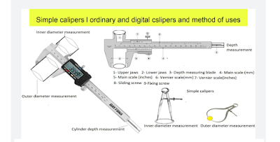
Simple calipers and vernier calipers, method of uses and calculations

Calipers: The calipers are very useful instruments. These instruments are used to measure the diameter of the cylinder, bore, bearing size, ...