Showing posts with label drafting. Show all posts

Monday, March 2, 2020

WORKING PROCEDURE OF RING FRAME MACHINE


WORKING PROCEDURE OF RING FRAME MACHINE:

The working procedure of the ring frame machine can be understood in the following steps:

CREELING:

The roving bobbins obtained from the simplex process is used as feed material in the ring frame. These roving bobbins are mounted on the bobbin holders of the creel. The creel is mounted on the top of the ring frame machine. The roving now passes through the guide bar which guides it toward the drafting system. The creel is equipped with automatic roving break stop motion. When a roving break occurs in any spindle during the process, the stop motion actuates immediately and stops the working of that particular spindle.

DRAFTING:

When the roving gets entered into the drafting zone, it is drafted according to the desired count of yarn to be spun. The drafting system is inclined at 45-50 degrees in the ring frame machine. The working performance of a drafting system of ring frame greatly affects the yarn quality.

The amount of draft to be employed in the ring frame depends upon the material to be processed. It normally ranges between 35 - 40 in the processing of cotton fibres and up to 50 in the processing of synthetic material. The drafting system plays a very important role in the performance of the ring frame process. The higher draft range of the ring frame machine helps to reduce the yarn cost because coarser roving can be used. Thus operation cost in simplex gets reduced. The drafting rollers are loaded with spring pressure to maintain the regular gripping of rollers.

Due to fewer fibres in the front drafting zone, the fibre strand has very poor strength. This situation necessitates providing enough guidance to the drafted material. This guidance is performed with the help of aprons. The double apron drafting arrangements with longer bottom aprons is the most widely used guiding system in all modern ring frame machines.  In order to be able to guide the fibres, the upper apron must be pressed with controlled force against the lower apron. A controlled spacing (exit opening), precisely adapted to the fibre volume is needed between the two aprons at the delivery for controlled force against bottom aprons. The long bottom aprons have the advantage in comparison with short aprons. The long aprons can be easily replaced when it gets damaged and there is less risk of choking with fluff.

TWISTING:

When the drafted fibres strand comes out from the front drafting rollers, it has very poor strength. A certain amount of twist is inserted into the fibres strand. This twist helps to hold the fibres together in the yarn. The twist is inserted into the yarn by spindle rotating at a very high speed. The traveller rotating on the spinning ring inserts one turn into the yarn after the completion of each revolution.

WINDING:

The yarn produced during the ring-spinning process gets wound on the ring bobbin simultaneously and continuously. This job is performed by the speed difference between spindle and traveller. The traveller drags with a spindle with the help of attached yarn to it. The traveller rotates at a slower speed than the spindle. The yarn gets wound on a ring bobbin. The traveller imparts a twist to the yarn. The traveller and spindle together help to wind the yarn on the bobbin. The length wound up on the bobbin corresponds to the difference in peripheral speeds of the spindle and traveller.  The difference in speed should correspond to the length delivered at the front drafting rollers. Since the traveller does not have its own drive, it gets dragged along behind by the spindle.

A yarn traverse guide is mounted on the movable ring rail. This traverse guide carries the yarn upward and downward during package formation. The traverse guide makes up and down movement with a movable ring rail. The layer traverse of the ring rail is also less than the full winding height of the empty ring bobbin. The ring rail, therefore, has to be raised slightly (shift traverse) after each layer has been wound.

A high balloon results in a large bobbin diameter leading to space problems. The larger balloon creates a higher air drag on the yarn. Thus higher yarn tension acts on the yarn which results in the form of more end breakages during the ring frame process. In order to avoid this problem, balloon control rings are used. It divides the balloon into two smaller sub-balloons. In spite of its large overall height, the double-balloon created in this way is thoroughly stable even at relatively low yarn tension.  Balloon control rings, therefore, help to run the machine with long spindles (longer lift) and at high spindle speed, but with lower yarn tension.

DOFFING:

Doffing is the process of replacing the filled ring bobbins with an empty bobbin. When the ring bobbins get full of yarn, these bobbins need to replace with empty bobbins. This job gets performed manually. It can be done automatically also. When doffing is performed, the machine is stopped first then thread guides are hinged up. Now bobbins are removed from the spindles and empty bobbins are put on the spindles. The thread guides are lowered again and the machine is restarted.

Please click on the below video link to watch the full article in Hindi:


You may also be interested in following articles:

Friday, October 18, 2019

DRAWING - IN PROCESS, A WEAVING PROCESS

DRAWING-IN PROCESS:

The drawing-in process comes just after the preparation of the weaver’s beam. The weaver’s beam is obtained from sectional warping or sizing. The drawing-in process mainly consists of two processes. The first process is called drafting and the second process is called denting. It is mostly performed manually but in large scale textile industries, automatic drawing-in machines are used, where more productivity is required. When the drop wires with closed D are used, the ends are drawn through the D of drop wires before the heald eye. The drawing-in process is applied for the execution of a new fabric design on the loom. When the fabric design is repeated regularly, the warp tying (knotting) process is applied to change a weaver’s beam. The tying process is done manually or with the help of the knotting machine.

Drafting:  


“A process of passing the end through the eye of heald wire or harness according to the draft (sequence of drafting the ends) is called drafting”. When the drafting is performed manually, two persons do this job. The person who selects the ends and presents them for drawing is called the reacher. The person who draws the ends through the eye of heald wire with the help of a drawing hook is called a drawer.

Denting:


When the drafting of the ends is completed, these ends are passed through the dent of the reed. We can say that “denting is the process of passing the ends through the dents of reed according to the denting order of the fabric to be woven”. It can be performed by a single person or two-person. In the case of two persons, one person selects the ends and presents them to the other person who passes these ends through the dents of the reed.

Tying (knotting) or piecing:

When the fabric design is repeated on the same loom after the weaver’s beam exhaustion, there is no need to perform the drawing-in process on that loom. The tying process is used to replace the exhausted weaver’s beam with a new weaver’s beam. Tying or knotting is the process of joining the ends of an exhausted weaver’s beam with the ends of the new weaver’s beam. It is performed manually or mechanically. When it is performed manually, it is called “piecing”. When it is performed mechanically, it is called “knotting”.

METHOD OF DRAFTING:

There is two methods of drafting which are given below:

• Manual drafting method

• Automatic drafting method

Manual or hand drafting method:

This method is performed manually. It is a too time-consuming process in the drawing-in process. Highly skilled persons are needed to perform this task. The required number of heald shafts are prepared. The heald wires are inserted into each heald shaft according to the total number of ends present in the weaver’s beam. These heald shafts are hung on the stand. Now weaver’s beam is put just behind the stand.  Each end of the barrel of the weaver’s beam rests on the two bearings fitted on the small iron stand. These bearing stands helps to rotate the weaver’s beam in any direction. Now the warp sheet passes over the aluminium pipe fitted across the full width of the drawing stand. If the beam is prepared on the sectional warping machine, it has the ends separation lease. The reacher clears the ends with the help of a dressing brush. If sized weaver’s beam is used, there is needed to fix the ends on their place with the help of half reed of suitable count. Before hanging the warp on the aluminium pipe, one or two layers of the warp sheet are unwound. Now the ends of the warp sheet are fixed with the help of gum tape. The half-metre length of the warp sheet is unwound again and another gum tape is put. Now half reed is inserted in the warp sheet between the two gum tapes fixed earlier on the warp sheet. This half reed is tied with the drawing stand. This half reed prevents changing the position ends in the warp sheet and end crossing in the sheet. Now reacher selects the end according to lease or half reed and presents it in front of the eye of the heald wire selected by the drawer. The drawer inserts the drawing hook into the eye of the heald wire and the reacher puts the selected end in the hook. When the drawer pulls the hook, the end also comes with a drawing hook, thus the end is drawn through the eye of heald wire. This action is repeated again and again till the completion of the drafting of the full warp sheet. When the drafting is completed, the end is passed through dents of reed. When one person does this process, he first selects the end, then inserts the denting stripe into the dent, then put the selected end into the slot of denting stripe. Now he grips the stripe with the help of his left hand under the reed and pulls the stripe. Thus end is passed through the dent of reed. This action is repeated till the completion of denting of the full warp beam.

 
Please click on the below video link to watch the full article in Hindi:


Featured Post

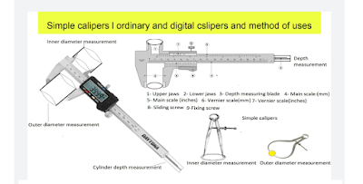
Simple calipers and vernier calipers, method of uses and calculations

Calipers: The calipers are very useful instruments. These instruments are used to measure the diameter of the cylinder, bore, bearing size, ...