Showing posts with label object of warp break stop motion. Show all posts

Monday, June 21, 2021

मैकेनिकल वार्प ब्रेक स्टॉप मोशन ( mechanical warp break stop motion )

 मैकेनिकल वार्प ब्रेक स्टॉप मोशन:

वार्प ब्रेक स्टॉप मोशन  एक सहायक लूम मोशन होता  है। एक वार्प ब्रेक स्टॉप मोशन  का मुख्य उद्देश्य करघे के संचालन के दौरान  वार्प एन्ड के टूटने पर तुरंत करघे को रोकना होता  है। कपड़े की गुणवत्ता और करघे की उत्पादकता में सुधार के लिए वार्प  ब्रेक स्टॉप मोशन बहुत महत्वपूर्ण भूमिका निभाता है। यदि कोई वार्प एन्ड  टूट जाता है और करघा चलता रहता है, तो वार्प  बीम से आने वाला टूटा हुआ वार्प एन्ड  ठीक तार की आंख के पीछे जमा होता रहता  है। इस यार्न के जमाव के कारण कई वार्प एन्ड टूट जाते हैं और इन टूटे हुए वार्प एंड्स  को फिर से हील्ड वायर के आईज और रिड के डेंट में भरने  में लंबा समय लगता है। इस प्रकार करघा दक्षता कम हो जाती है। जब वार्प एन्ड के टूटने  की स्थिति में करघा चलता रहता है, तो उत्पादित होने वाला कपड़ा ख़राब हो जाता है। इस प्रकार कपड़े की गुणवत्ता  भी प्रभावित होती है। वार्प  ब्रेक स्टॉप मोशन उत्पादकता बढ़ाने और करघे पर बुने जाने वाले कपड़े की गुणवत्ता में सुधार करने में मदद करता है।


वार्प ब्रेक स्टॉप मोशन के प्रकार:

वार्प ब्रेक स्टॉप मोशन के प्रकार नीचे दिए गए हैं:

1 - मैकेनिकल वार्प ब्रेक स्टॉप मोशन

2 - विद्युत वार्प ब्रेक स्टॉप मोशन

3 - इलेक्ट्रॉनिक वार्प ब्रेक स्टॉप मोशन

यांत्रिक वार्प ब्रेक स्टॉप मोशन की संरचना:

इस तंत्र में एक रिसीप्रोकेटिंग बार, ऑसिलेटिंग डिवाइस नॉक-ऑफ डिवाइस और ड्रॉप वायर होते हैं।

 पूर्ण रेसिप्रोकेटिंग  बार तीन घटकों से बना होता है । फिक्स्ड  बाहरी बार में दो प्लेट होते हैं।

रेसिप्रोकेटिंग  बार, फिक्स्ड  बाहरी बार की इन दो प्लेटों के बीच स्लाइड करता है। बाहरी बार और रेसिप्रोकेटिंग  बार के शीर्ष किनारे को कैस्टिलेटेड किया जाता है।

यह सुनिश्चित करने के लिए कि ड्रॉप वायर दोनों बार के सबसे निचले कट-आउट पॉइंट में गिरेगा, यह आवश्यक है कि रिसीप्रोकेटिंग बार, दो फिक्स्ड  बाहरी बार से थोड़ा अधिक ऊँची  हो।

कैस्टिलेटेड बार की संख्या वार्प बीम में उपयोग किए जाने वाले प्रति इंच वार्प एंड्स  की संख्या पर निर्भर करती है। 4 - 8 कैस्टिलेटेड बार सामान्य रूप से उपयोग किए जाते हैं।

प्रत्येक कैस्टिलेटेड बार का एक सिरा पिन के माध्यम से ड्राइव मैकेनिज्म से जुड़ जाता है।

कैस्टिलेटेड बार ड्रॉप वायर्स  के  स्लॉट  के बीच से गुजरते हैं। रेसिप्रोकेटिंग  बार फोर्क्ड  ब्रैकेट से जुड़ा हुआ होता  है।

यह फोर्क्ड  ब्रैकेट एक फलक्रम लीवर से जुड़ा हुआ होता  है। यह फलक्रम लीवर कैम लीवर से कटे हुए रोक्किंग डायमंड  के आकार  के निचले भाग में होता है।

फलक्रम लीवर का निचला सिरा स्प्रिंग-लोडेड होता है। रिलीज ट्रिप लीवर का एक सिरा स्प्रिंग-लोडेड लीवर पर टिका होता है।

जैसा कि नीचे दिए गए चित्र में दिखाया गया है, रिलीज कैच ट्रिप लीवर फलक्रम्ड होता है।

रिलीज कैच ट्रिप लीवर का दूसरा सिरा लिफ्टिंग कैच के निचले सिरे के सामने टिकी हुई होती है।

दोलन तंत्र स्प्रोकेट व्हील और चेन के माध्यम से क्रैंकशाफ्ट से जुड़ा होता है।

कैम लीवर का एक सिरा एक्सेंट्रिक कैम से  जुड़ा होता है।

यांत्रिक वार्प ब्रेक स्टॉप मोशन का कार्य सिद्धांत:

कैम लीवर और एक्सेंट्रिक  कनेक्टिंग रॉड के माध्यम से जुड़े हुए होते  हैं। जब एक्सेंट्रिक  घूमता है, तो यह कैम लीवर को दोलन गति प्रदान करता है।

फलक्रम लीवर बीच में कैम लीवर से जुड़ा होता है। फलक्रम लीवर के शीर्ष पर एक फोर्क्ड  ब्रैकेट जुड़ा हुआ होता है।

जब कैम लीवर दोलन करता है, तो फोर्क्ड  ब्रैकेट भी दोलन करता है। चूँकि रेसिप्रोकेटिंग  बार का एक सिरा एक कांटेदार ब्रैकेट से जुड़ा होता है ताकि रेसिप्रोकेटिंग  बार भी आगे-पीछे हो सके।

जब करघा संचालित होता है, तो ड्रॉप वायर ताना तनाव के कारण वार्प एंड्स  पर टिका होता है।

रेसिप्रोकेटिंग  बार के शीर्ष किनारे और ड्रॉप वायर के स्लॉट के बीच पर्याप्त गैप होता है ।

यह गैप  दो फिक्स्ड  बाहरी बार्स  के बीच रेसिप्रोकेटिंग  बार के आगे और पीछे की मोशन  के लिए एक मुक्त मार्ग बनाता  है।

इस स्थिति में रिलीज कैच ट्रिप लीवर की स्थिति नहीं बदलती है और लूम चलता रहता है।

जब वार्प का धागा  टूटता  है, तो ड्रॉप वायर तुरंत रेसिप्रोकेटिंग  बार के कट-आउट में गिर जाता है।

ड्रॉप वायर रेसिप्रोकेटिंग  बार के आगे और पीछे की गति में बाधा उत्पन्न करता है।

फलक्रम लीवर का स्प्रिंग-लोडेड सिरा इस स्थिति में ऊपर उठता है क्योंकि यह साइड-वाइज रॉक   नहीं कर  सकता है।

रिलीज कैच ट्रिप लीवर भी ऊपर उठ  जाता है। अब इस लीवर का बाहरी सिरा नीचे  गिरता है और लिफ्टिंग कैच को कैम लीवर के बाहरी सिरे पर खिसकने में मदद  देता है।

जैसे ही कैम लीवर का यह सिरा ऊपर उठता है, यह लिफ्टिंग कैच को ऊपर उठाता है, और इस तरह नॉक ऑफ लीवर स्लाइड करता है और एक तार के माध्यम से करघे के सामने के छोर पर स्ले से  जुड़ी हुई कैच  को शुरुआती हैंडल यूनिट के प्रोजेक्शन  के अनुरूप उठाया जाता हैऔर  करघा केस्टार्टिंग हैंडल को  नॉक ऑफ कर देता है ।

Saturday, April 3, 2021

Electrical or electromechanical warp break stop motion


Electrical warp break stop motion:

The electrical warp break stop motion works more efficiently than the mechanical warp break stop motion. Actually, this stop motion is not fully electrically controlled so that it may be termed as electromechanical warp break stop motion. Warp break is felt by the drop wire and the electromagnet is actuated by the electrical circuit. 
Structure of electrical warp break stop motion:
A single-acting or double-acting cam is mounted on the bottom shaft. A knock off of lever rests upon the cam. A knock off bar is attached with the L shape lever. One end of L shape lever is connected with starting handle. A power supply switch is attached with starting handle.  Both the points of this power supply switch get touched to each other during the normal running situation. One end of this power supply switch is connected with one terminal of the solenoid magnet coil. The other terminal of the solenoid gets connected with the copper part of the electrode.  The iron part of the electrode is connected with the earth. 
The electrode is made of three components as shown in the below figure. The outer part of this electrode is made of iron and the middle part is made of copper strip. Insulation material is used between the iron part and copper part. This insulation separates both the components from each other. It means the electric current does not pass from the outer part to the middle part when the outer part is connected with the electric supply. This electrode is inserted through the slot of the drop wire. The warp yarn is drawn through the eye of the drop wire. The number of electrodes being used depends upon the number of warp ends per inch getting used. 
A transformer is used to reduce the power supply. Normally, 240 v input is supplied to the transformer. This transformer reduces the supply voltage. 12 or 24 volts output is achieved by this transformer.


Working principle of electrical warp stop motion:
When the loom runs in normal working condition and the starting handle gets engaged in the slot. Both points of the power supply switch get touched to each other. The warp yarn tension keeps the drop wire in an up position and the top edge of the drop wire don't get touched with the copper part of the electrode.  The cam mounted on the bottom shaft gets rotated regularly and it imparts up and down movement to the knock off lever but this knock-off lever doesn't touch with the bar mounted on the L shape lever.
Now suppose that the warp end gets broken, the drop wire falls upon the electrode. As the drop wire falls, the power supply of the solenoid gets on. The solenoid gets energised immediately.  The solenoid magnet attracts the bar mounted on the L shape lever in the upward direction. As this bar lifts up, it comes in front of a knock off lever. The knock-off lever pushes this bar. Since the L shape lever gets connected with the starting handle so that the starting handle is also pushed by the L shape lever. The starting handle gets out of its slot and the contact between both points of the power supply switch get broken and looms gets stopped immediately. 
If a single-acting cam is used, the loom gets stopped after two loom revolutions. The double-acting cam stops the loom after one loom revolution. 

Please click on the below video link to watch the full topic in Hindi:


You may also be interested in the following articles:


Let - off motion, secondary loom motion

Take - up motion, a secondary loom motion

Shedding motion, a primary loom motion

Picking motion, a primary loom motion

Beating motion, a primary loom motion

Schematic diagram of loom

Related articles:


Wednesday, March 31, 2021

Mechanical warp break stop motion

          Mechanical warp break stop motion:

The warp stop motion is an auxiliary loom motion. The main objective of a warp stop motion is to stop the loom immediately when an end breakage occurs during the loom operation. The warp break stop motion plays a very important role to improve the quality of the fabric and the productivity of the loom. If an end breakage occurs and the loom gets continued to run, the broken end coming from the warp beam gets accumulated behind the eye of the heald wire. This yarn deposition causes multiple end breakages and this multiple ends breakage takes a long time to redraw these broken ends. Thus loom efficiency gets decreased. When the loom gets continues to run in case of end breakage, the fabric getting produced becomes defective. Thus the quality of the fabric gets affected. The warp break stop motion helps to increase productivity and improve the quality of the fabric getting woven on the loom.

Types of warp break stop motions:

The types of warp break stop motions are given below:

1 - Mechanical warp break stop motion

2 - Electrical warp break stop motion

3 - Electronic warp break stop motion

Structure of mechanical warp break stop motion

This mechanism consists of a reciprocating bar, oscillating device knock-off device, and drop wire. 

The complete reciprocating bar made of three components. The fixed outer bar consists of two plates. 

The reciprocating bar slides between these two plates of fixed outer bar. The top edge of the outer bar and reciprocating bar gets castillated. 

In order to ensure that the drop wire will fall into the lowest cut-out point of both bars, it is necessary for the reciprocating bar to be slightly higher than the two fixed outer bars. 

The number of castillated bars depends upon the number of ends per inch used in the warp beam. 4 - 8 castillated bars are normally used. 

The one end of each castillated bar gets connected with the drive mechanism through a pin. 

The castillated bars pass through the slot in the drop wire. The reciprocating bar is connected with the forked bracket. 

This forked bracket is attached with a fulcrum lever. This fulcrum lever held in the bottom of the rocking diamond-shaped cut out of the cam lever. 

The lower end of the fulcrum lever gets spring-loaded. The one end of the release trip lever rests upon the spring-loaded lever. 

The release catch trip lever gets fulcrummed as shown in the below figure. 

The other end of the release catch trip lever rests in front of the lower end of the lifting catch.  

The oscillating mechanism is connected to the crankshaft through the sprocket wheel and chain. 

The one end of the cam lever is connected to the eccentric.


Working principle of mechanical warp stop motion:

The cam lever and eccentric are connected through the connecting rod. When the eccentric rotates, it imparts oscillating motion to the cam lever.  

The fulcrum lever is connected to the cam lever in the middle. A forked bracket is attached at the top of the fulcrum lever.

When the cam lever oscillates, the forked bracket also oscillates. Since the one end of the reciprocating bar is connected with a forked bracket so that the reciprocating bar also makes back and forth movement. 

When the loom operates, the drop wire rests upon the warp end due to warp tension. 

Enough clearance between the top edge of the reciprocating bar and the slot of drop wire. 

This clearance makes a free passage for back and forth movement of the reciprocating bar between two fixed outer bars. 

The position of the release catch trip lever doesn't change in this situation and the loom gets continues to run. 

When the end breakage occurs, the drop wire falls immediately in the cut-out of the reciprocating bar. 

The drop wire creates a hurdle in the back and forth motion of the reciprocating bar. 

The spring-loaded end of the fulcrum lever rises in this situation because it cannot be rock side-wise. 

The release catch trip lever also rises. Now the outside end of this lever falls and allows the lifting catch to slip over the outside end of the cam lever. 

As this end of cam lever rises, it raises the lifting catch, and thus the knock off lever slides and through a wire further catch attached to sley at the front end of the loom is raised into line with a projection of the starting handle unit for the loom to be knocked off. 

Please click on the below video link to watch the full topic in Hindi:


Related articles:


Featured Post

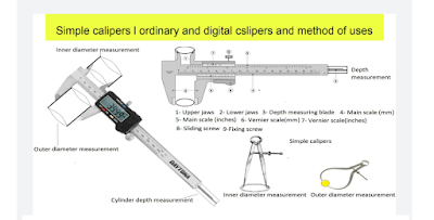
Simple calipers and vernier calipers, method of uses and calculations

Calipers: The calipers are very useful instruments. These instruments are used to measure the diameter of the cylinder, bore, bearing size, ...