Showing posts with label working of electrical warp break stop motion. Show all posts
Showing posts with label working of electrical warp break stop motion. Show all posts
Friday, April 9, 2021
Saturday, April 3, 2021
Electrical or electromechanical warp break stop motion
Electrical warp break stop motion:
The electrical warp break stop motion works more efficiently than the mechanical warp break stop motion. Actually, this stop motion is not fully electrically controlled so that it may be termed as electromechanical warp break stop motion. Warp break is felt by the drop wire and the electromagnet is actuated by the electrical circuit.
Structure of electrical warp break stop motion:
A single-acting or double-acting cam is mounted on the bottom shaft. A knock off of lever rests upon the cam. A knock off bar is attached with the L shape lever. One end of L shape lever is connected with starting handle. A power supply switch is attached with starting handle. Both the points of this power supply switch get touched to each other during the normal running situation. One end of this power supply switch is connected with one terminal of the solenoid magnet coil. The other terminal of the solenoid gets connected with the copper part of the electrode. The iron part of the electrode is connected with the earth.
The electrode is made of three components as shown in the below figure. The outer part of this electrode is made of iron and the middle part is made of copper strip. Insulation material is used between the iron part and copper part. This insulation separates both the components from each other. It means the electric current does not pass from the outer part to the middle part when the outer part is connected with the electric supply. This electrode is inserted through the slot of the drop wire. The warp yarn is drawn through the eye of the drop wire. The number of electrodes being used depends upon the number of warp ends per inch getting used.
A transformer is used to reduce the power supply. Normally, 240 v input is supplied to the transformer. This transformer reduces the supply voltage. 12 or 24 volts output is achieved by this transformer.

Working principle of electrical warp stop motion:
When the loom runs in normal working condition and the starting handle gets engaged in the slot. Both points of the power supply switch get touched to each other. The warp yarn tension keeps the drop wire in an up position and the top edge of the drop wire don't get touched with the copper part of the electrode. The cam mounted on the bottom shaft gets rotated regularly and it imparts up and down movement to the knock off lever but this knock-off lever doesn't touch with the bar mounted on the L shape lever.
Now suppose that the warp end gets broken, the drop wire falls upon the electrode. As the drop wire falls, the power supply of the solenoid gets on. The solenoid gets energised immediately. The solenoid magnet attracts the bar mounted on the L shape lever in the upward direction. As this bar lifts up, it comes in front of a knock off lever. The knock-off lever pushes this bar. Since the L shape lever gets connected with the starting handle so that the starting handle is also pushed by the L shape lever. The starting handle gets out of its slot and the contact between both points of the power supply switch get broken and looms gets stopped immediately.
If a single-acting cam is used, the loom gets stopped after two loom revolutions. The double-acting cam stops the loom after one loom revolution.
Please click on the below video link to watch the full topic in Hindi:
You may also be interested in the following articles:
Let - off motion, secondary loom motion
Take - up motion, a secondary loom motion
Shedding motion, a primary loom motion
Picking motion, a primary loom motion
Beating motion, a primary loom motion
Schematic diagram of loom
Related articles:
Subscribe to:
Posts (Atom)
Featured Post
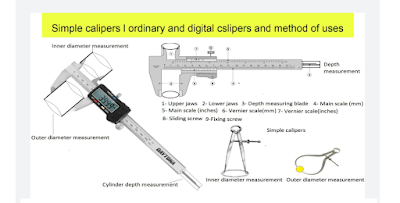
Simple calipers and vernier calipers, method of uses and calculations
Calipers: The calipers are very useful instruments. These instruments are used to measure the diameter of the cylinder, bore, bearing size, ...
-
 If you are searching for genuine hand woven, sustainable, and eco – friendly warm shawls, stoles, and scarves, the Himalayan weavers is off...
 -
 please click on the below link to read this article in Hindi यार्न की परिभाषा और यार्न के विभिन्न प्रकार या यार्न का वर्गीकरण VARIOUS TYPE...
 -
 CARDING: The carding is the second process of spinning which converts fed material (lap) into the uniform strand of fibres called “...
 -
 please click on the below link to read this article in Hindi एक सिस्टम से दूसरे सिस्टम में यार्न काउंट का रूपांतरण CONVERSION OF YARN COUN...