Sunday, July 18, 2021
Friday, July 16, 2021
Monday, May 31, 2021
रैपियर वेफ्ट इंसर्शन सिस्टम l रैपियर लूम के प्रकार l वेफ्त यार्न पैसेज और रैपियर वेफ्ट इंसर्शन सिस्टम का कार्य सिद्धांत
रैपियर लूम वेफ्ट इंसर्शन सिस्टम:
यह सबसे बहुमुखी वेफ्ट इंसर्शन सिस्टम होता है। इस लूम पर वेफ्ट यार्न काउंट की एक बहुत विस्तृत सीमा होती है। आप बड़ा बदलाव किए बिना बहुत मोटे से बहुत महीन धागे में वेफ्ट के रूप में डाल सकते हैं। वेफ्ट इंसर्शन के दौरान बाने के धागे की यात्रा लगातार नियंत्रित होती जाती है। कपड़े की चौड़ाई को मशीन के स्पेसिफिकेशन्स की सीमा के भीतर समायोजित किया जा सकता है। कपड़ा उद्योग में रैपियर लूम का व्यापक रूप से उपयोग किया जाता है। बाने के रंगों की संख्या 8 से 16 के बीच होती है।
रैपियर लूम का वर्गीकरण:
एक रैपियर लूम को इस्तेमाल किए गए वेफ्ट इंसर्शन मैकेनिज्म के अनुसार निम्न वर्गों में वर्गीकृत किया जा सकता है।
सिंगल रैपियर लूम:
वह रैपियर लूम जिसमें शेड में बाने के धागे को डालने के लिए केवल एक रैपियर का उपयोग किया जाता है, सिंगल रैपियर लूम कहलाता है। रैपियर की तय की गई दूरी लूम में इस्तेमाल किए गए रीड स्पेस के बराबर होती है। इस तरह का लूम बहुत कम गति से काम करता है। वार्प यार्न रैपियर पर उच्च दबाव डालता है।
डबल रैपियर लूम :
वह रैपियर लूम जिसमें दो रैपियर की मदद से शेड में वेफ्ट इंसर्शन किया जाता है, इस प्रकार के लूम को डबल रैपियर लूम के रूप में जाना जाता है। प्रत्येक रैपियर लूम में प्रयुक्त रीड स्पेस की आधी दूरी तय करता है। डबल रैपियर लूम बहुत तेज गति से चलता है। रैपियर पर वार्प के धागे का दबाव अधिकतम सीमा तक कम हो जाता है।
फ्लेक्सिबल रेपियर लूम :
इस तरह के लूम में ग्रिपर्स को टेफ्लॉन और कार्बन फैब्रिक से बने लचीले रिबन या टेप पर लगाया जाता है। चूंकि रिबन की लंबाई डबल रैपियर लूम में उपयोग किए गए रीड स्पेस के लगभग बराबर होती है और प्रत्येक रिबन की लंबाई का लगभग आधा हिस्सा वेफ्ट इंसर्शन के दौरान शेड में प्रवेश करता है ताकि रिबन की शेष आधी लंबाई होलो रैपियर गाइड के अंदर वापस चली जाए। जब ग्रिपपेर्स स्ले सेण्टर की स्थिति में पहुंच जाती है। यह शेष लंबाई वह लंबाई है जो बाने डालने के दौरान शेड में प्रवेश नहीं करती है। यह कार्य रैपियर रिबन के लचीलेपन के कारण संभव हो पाता है। लचीले रैपियर रिबन के उपयोग के कारण, इस प्रकार के लूम को फ्लेक्सिबल रैपियर लूम कहा जाता है। यह लूम रिजिड रैपियर लूम की तुलना में अधिक आरपीएम पर चल सकता है। इस तरह के लूम कम जगह घेरते हैं।
रिजिड रेपियर लूम :
यदि ग्रिपर्स को किसी रैपियर लूम में रिजिड रैपियर रैक पर लगाया जाता है, तो इसे रिजिड रैपियर लूम के रूप में जाना जाता है। रिजिड रैपियर, फ्लेक्सिबल रैपियर लूम की तुलना में धीमी गति से चलता है। रिजिड र रैपियर लूम, फ्लेक्सिबल रैपियर लूम की तुलना में अधिक स्थान घेरता है।
नेगेटिव वेफ्ट ट्रांसफर रैपियर लूम:
यदि वेफ्ट टेंशन की मदद से रैपियर ग्रिपर्स के ग्रिपिंग जबड़ों के बीच वेफ्ट यार्न को पकड़ाया जाता है और वेफ्ट ट्रांसफर चक्र के दौरान प्रत्येक ग्रिपर के ग्रिपिंग जॉ को खोलने और बंद करने के लिए किसी भी अतिरिक्त तंत्र का उपयोग नहीं किया जाता है, तो इस तरह के वेफ्ट ट्रांसफर को नेगेटिव वेफ्ट ट्रांसफर कहा जाता है। यदि वेफ्ट इंसर्शन के दौरान लूम में नेगेटिव वेफ्ट ट्रांसफर होता है, तो उस लूम को नेगेटिव वेफ्ट ट्रांसफर रैपियर लूम कहा जाता है।
पॉजिटिव वेफ्ट ट्रांसफर रैपियर लूम:
यदि वेफ्ट ट्रांसफर के पूरे चक्र के दौरान प्रत्येक रैपियर के ग्रिपिंग जबड़ों को एक अतिरिक्त तंत्र की मदद से खोला और बंद किया जाता है, तो इस तरह के वेफ्ट इंसर्शन को पॉजिटिव वेफ्ट ट्रांसफर के रूप में जाना जाता है। पॉजिटिव वेफ्ट ट्रांसफर से लैस लूम को पॉजिटिव वेफ्ट ट्रांसफर रैपियर लूम कहा जाता है।
रैपियरलूम में बाने के धागे का मार्ग:
वेफ्ट पैकेज वेफ्ट क्रील पर लगा होता है। उपयोग किए जा रहे बाने के धागों में रंगों की संख्या के अनुसार बाने के पैकेजों की संख्या का उपयोग किया जाता है। यार्न पहले थ्रेड गाइड से गुजरता है और इसके बाद वेफ्ट क्रील पर लगे वेफ्ट टेंशनर से गुजरता है। इसके बाद, वेफ्ट यार्न वेफ्ट एकुमुलेटर से होकर गुजरता है। यह वेफ्ट एकुमुलेटर स्थिर तनाव पर यार्न की निरंतर आपूर्ति सुनिश्चित करता है। जब बाने का पैकेज ख़त्म होने की स्थिति के करीब पहुंच जाता है, तो यार्न का तनाव अधिकतम हो जाता है। वेफ्ट एकुमुलेटर इस प्रभाव को बेअसर करता है और पूरे पैकेज में बाने के तनाव को स्थिर रखता है। वेफ्ट क्रील पर लगा वेफ्ट टेंशनर एकुमुलेटर पर आसन्न यार्न कॉइल के ओवरलैपिंग को रोकता है। उपयोग किए गए वेफ्ट एकुमुलेटर्स की संख्या बाने के धागे में इस्तेमाल होने वाले रंगों की संख्या के बराबर हो जाती है।

अब यार्न फिलिंग डिटेक्टर से होकर गुजरता है। फिलिंग डिटेक्टर में या तो सिंगल वेफ्ट सेंसिंग चैनल या मल्टी वेफ्ट सेंसिंग चैनल होते हैं। फिलिंग डिटेक्टर एक तरफ से दूसरी तरफ वेफ्ट की पूरी यात्रा की निगरानी करता है। यदि वेफ्ट इंसर्शन विफल हो जाता है या लंबाई में छोटा रह जाता है, तो यह लूम को तुरंत बंद कर देता है। अगले क्रम में वेफ्ट यार्न थ्रेड गाइड से होकर गुजरता है जो बाने के धागों को अलग रखने में मदद करता है। यह विभिन्न बाने के धागों को आपस में उलझने से भी रोकता है। थ्रेड गाइड में कई सिरेमिक आईज लगी होती हैं।
अंत में, बाने का धागा वेफ्ट सिलेक्टर फिंगर की आई से होकर गुजरता है। नियंत्रण कंप्यूटर में वेफ्ट पैटर्न फीडिंग के अनुसार वेफ्ट सिलेक्शन फिंगर का चयन होता है।
रैपियर वेट इंसर्शन सिस्टम का कार्य सिद्धांत:
बाने के धागे को कैच सेल्वेज पकड़ कर रखता है।इस कैच को सेल्वेज बनाने के लिए दस से बीस धागो का इस्तेमाल किया जाता है। धागो को या तो एक अलग रील पर लपेटा जाता है या एक कैच सेल्वेज क्रील का उपयोग किया जाता है जिसमें आवश्यक छोटे यार्न पैकेज लगाए जाते हैं। कैच सेल्वेज में हमेशा प्लेन वीव का उपयोग किया जाता है। रीड के एक सिरे के बहुत करीब टेम्पल के ब्रैकेट पर लगाई गई एक कैच प्लेट, बाने के धागे को रीड की ओर जाने से रोकती है।
जब रीड आखिरी डाली गई पिक को बीत कर देता है, तो एक नया वेफ्ट इंसर्शन चक्र शुरू होता है। सबसे पहले, वेफ्ट सिलेक्टर फिंगर गिरती है, और वेफ्ट यार्न इंसर्ट ग्रिपर के सामने आता है। बाने का धागा रैपियर गाइड को टच करने लगता है
रैपियर स्ले सेंटर की ओर यात्रा करना शुरू कर देता है और रिसीविंग रैपियर भी स्ले सेंटर की ओर यात्रा करना शुरू कर देता है। रिसीविंग रैपियर पहले चलना शुरू करता है। जब ग्रिपर वेफ्ट यार्न के नीचे से गुजरता है, तो यार्न इंसर्ट ग्रिपर के स्लॉट में प्रवेश कर जाता है। ग्रिपर के ग्रिपिंग प्रेशर को इस तरह से समायोजित किया जाता है कि यह इंसर्ट ग्रिपर के ऊपरी और निचले ग्रिपिंग जबड़ों के बीच वेफ्ट यार्न में प्रवेश करने में सहायता करता है। यार्न टेंशनर को समायोजित करके एक उपयुक्त वेफ्ट यार्न टेंशन भी प्राप्त किया जाता है। बाने का धागा कम से कम ग्रिपिंग जबड़ों के बीच तक पहुंचना चाहिए। इंसर्ट रैपियर के ग्रिपिंग जबड़ों के बीच कोई यार्न स्लिपेज नहीं होना चाहिए। जब इंसर्ट ग्रिपर शेड में प्रवेश करना शुरू करता है, तो फिलिंग कटर बाने के धागे को काट देता है। रैपियर गाइड के एक छोर पर इंसर्ट रैपियर के प्रवेश बिंदु के पास एक वेट यार्न सपोर्ट गाइड लगा होता है। यह यार्न गाइड रीड और वेफ्ट यार्न के बीच एक आवश्यक गेप बना कर रखता है। यह रीड की क्षति को भी रोकता है।

दोनों रेपियर स्ले सेंटर की ओर यात्रा करते हैं। रिसीविंग रैपियर सबसे पहले स्ले सेंटर पर पहुंचता है और वहां ड्वेल पीरियड में रेस्ट करता है। रिसीविंग रैपियर इंसर्ट ग्रिपर से वेफ्ट यार्न प्राप्त करने के लिए तैयार हो जाता है और वह वहीं इंतजार करता है। अब इंसर्ट रैपियर स्ले सेंटर तक पहुंचता है और इंसर्ट ग्रिपर में जकड़ा हुआ धागा रिसीविंग ग्रिपर के हुक की नोक को पार कर जाता है। सेटिंग के दौरान रिसीविंग ग्रिपर के हुक की नोक और वेफ्ट यार्न के बीच में तीन मिमी की गैप सुनिश्चित की जाती है। जैसे ही इंसर्ट ग्रिपर ड्वेल पीरियड में आता है, रिसीविंग ग्रिपर फैब्रिक सेल्वेज की ओर बढ़ना शुरू कर देता है। रिसीविंग ग्रिपर का हुक इन्सर्ट ग्रिपर से बाने के धागे को खींचता है। चूंकि रिसीविंग ग्रिपर में इंसर्ट ग्रिपर की तुलना में थोड़ा अधिक ग्रिपिंग प्रेशर होता है, जिससे यार्न रिसीविंग ग्रिपर के ग्रिपिंग जबड़ों के बीच प्रवेश कर जाता है। इंसर्ट ग्रिपर भी अपनी ड्वेल की अवधि बीतने के बाद फैब्रिक सेल्वेज की ओर बढ़ना शुरू कर देता है। रिसीविंग ग्रिपर पहले शेड से बाहर आता है। रैपियर गाइड में फिट किया गया ग्रिपर ओपनर ग्रिपिंग जबड़ों को खोलता है और कैच सेल्वेज के बाहर बाने के धागे को छोड़ता है। एक सक्शन नोजल अपने अंदर वेफ्ट के धागे की पूंछ को खींच लेता है और इसे टाइट रखने में मदद करता है। कैच सेल्वेज के धागे उसी समय में एक दूसरे को क्रॉस करते है और बाने के धागे को मजबूती से पकड़ लेते है। इस अवधि के दौरान इन्सर्ट रैपियर भी शेड से बाहर आ जाता है। अब बाने के धागों को रीड द्वारा बीत किया जाता है और वेफ्ट कैच प्लेट द्वारा बाने के धागे को फिर से पकड़ लिया जाता है। यह चक्र लगातार दोहराया जाता है।
Sunday, May 30, 2021
रैपियर वेफ्ट ट्रांसफर प्रक्रिया के प्रकार, नेगेटिव वेफ्ट ट्रांसफर और पॉजिटिव वेफ्ट ट्रांसफर( types weft transfer method in rapier loom, positive weft transfer and negative weft transfer
रैपियर वेफ्ट ट्रांसफर प्रक्रिया:
रैपियर लूम में वेफ्ट ट्रांसफर की प्रक्रिया ठीक उसी तरह है जैसे रिले रेस में बैटन चेंज होता है । जब दोनों रैपियर स्ले सेंटर पोजीशन में पहुंच जाते हैं, तो रिसीविंग ग्रिपर इंसर्ट ग्रिपर से वेफ्ट यार्न प्राप्त करता है। इन्सर्ट ग्रिपर से रिसीविंग ग्रिपर को वेफ्ट यार्न के ट्रांसफर को रैपियर लूम में वेफ्ट ट्रांसफर प्रक्रिया कहा जाता है।
रैपियर वेफ्ट ट्रांसफर के प्रकार:
रैपियर वेफ्ट इंसर्शन सिस्टम में निम्नलिखित प्रकार के वेफ्ट ट्रांसफर मेथड का इस्तेमाल किया जाता है।
1 - नेगेटिव रैपियर वेफ्ट ट्रांसफर मेथड।
2 - सकारात्मक रेपियर ।वेफ्ट ट्रांसफर विधि
नकारात्मक वेफ्ट स्थानांतरण विधि:
नेगेटिव वेफ्ट ट्रांसफर विधि में, वेफ्ट ट्रांसफर प्रक्रिया के दौरान दोनों ग्रिपर्स के ग्रिपिंग जॉ को खोलने के लिए ओपनिंग मैकेनिज्म का उपयोग नहीं किया जाता है। वेफ्ट ट्रांसफर दोनों ग्रिपर्स के वेफ्ट टेंशन और ग्रिपिंग प्रेशर के कारण होता है। रिसीविंग ग्रिपर का ग्रिपर प्रेशर इंसर्ट ग्रिपर की तुलना में थोड़ा अधिक रखा जाता है। इंसर्ट ग्रिपर के ग्रिपिंग प्रेशर के अनुसार वेफ्ट टेंशन भी समायोजित किया जाता है।
लचीले रिबन पर लगे ग्रिपर गाइड टीथ द्वारा बनाए गए एक निश्चित मार्ग के माध्यम से रेसिप्रोकेटिंग गति करते हैं। ये गाइड टीथ ग्रिपर के लिए एक उचित और निश्चित मार्ग को उपलब्द्ध कराते हैं। ये गाइड टीथ ग्रिपर को निश्चित मार्ग से बाहर जाने से भी रोकते हैं। रिसीविंग ग्रिपर बी सबसे पहले स्ले सेंटर तक पहुंचता है और इंसर्ट ग्रिपर से वेफ्ट यार्न प्राप्त करने के लिए तैयार हो जाता है। यह रिसीविंग ग्रिपर अपने ड्वेल अवधि में आराम करता है। वेफ्ट यार्न से लोडेड इंसर्ट ग्रिपर ए स्ले सेंटर पोजीशन पर पहुंचता है। जब इंसर्ट ग्रिपर वेफ्ट ट्रांसफर पोजीशन सी तक पहुंचता है, तो इंसर्ट ग्रिपर द्वारा ले जाया गया यार्न ग्रिपर हुक ई की नोक को पार कर जाता है। जैसे ही इंसर्ट ग्रिपर की ड्वेल अवधि शुरू होती है, रिसीविंग ग्रिपर उसी समय फैब्रिक सेल्वेज की ओर बढ़ना शुरू कर देता है। चूंकि रिसीविंग ग्रिपर का ग्रिप्पिंग प्रेशर इन्सर्ट ग्रिपर की तुलना में थोड़ा अधिक रखा जाता है ताकि यह पकड़ने वाले जबड़े एच के बीच बाने के धागे को पकड़ने में सफल हो जाए और वेफ्ट यार्न को फैब्रिक सेल्वेज की ओर ले जाए। नीचे दी गई तस्वीर में दिखाए गए नकारात्मक रैपियर वेफ्ट ट्रांसफर का योजनाबद्ध आरेख को देखिये:

सकारात्मक वेफ्ट स्थानांतरण विधि:
यह वेफ्ट हस्तांतरण विधि अधिक विश्वसनीय, कुशल और परिष्कृत होती है है। बहुत महीन फिलामेंट यार्न से लेकर बहुत ऊंचे मोटे काउंट के यार्न को बिना किसी परेशानी के सफलतापूर्वक डाला जा सकता है।
पॉजिटिव रैपियर वेफ्ट ट्रांसफर मेथड में दोनों ग्रिपर्स के ग्रिपिंग जॉ को मैकेनिकल ओपनिंग सिस्टम की मदद से खोला जाता है। दोनों ग्रिपर्स के ग्रिपिंग जॉ समय के अनुसार खुलते और बंद होते हैं।
डोर्नियर लूम निर्माता द्वारा सबसे कुशल सकारात्मक रैपियर वेफ्ट ट्रांसफर विकसित किया गया है।
इस सिस्टम में, ग्रिपर को कठोर रैपियर रैक पर लगाया जाता है।
वेफ्ट इंसर्शन के पूरे चक्र के दौरान ग्रिपर्स के ग्रिपिंग जॉ अतिरिक्त मैकेनिज्म की मदद से यांत्रिक रूप से खुलते और बंद होते हैं। खाली रिसीविंग ग्रिपर पहले स्ले सेंटर पोजीशन की ओर बढ़ना शुरू करता है।
जैसे ही वेफ्ट इंसर्शन चक्र शुरू होता है, वेफ्ट सिलेक्शन फिंगर प्रोग्राम कंप्यूटर में वेफ्ट पैटर्न के अनुसार गिरती है। अब इंसर्ट ग्रिपर स्ले सेंटर की ओर बढ़ना शुरू कर देता है। इंसर्ट ग्रिपर के ग्रिपिंग जॉ को ग्रिपर ओपनर की मदद से खोला जाता है। जैसे ही इंसर्ट ग्रिपर स्ले सेंटर की ओर थोड़ा आगे बढ़ता है, वेफ्ट यार्न ग्रिपिंग जॉ के बीच आ जाता है। अब पकड़ने वाले जबड़े बंद हो जाते हैं। ट्रांसफर चक्र आगे बढ़ता है और दोनों ग्रिपर शेड में प्रवेश कर जाते हैं।
जैसे ही रिसीविंग ग्रिपर वेफ्ट ट्रांसफर की स्थिति में पहुंचता है, यह आराम की स्थिति में आ जाता है। ग्रिपर ओपनर रिसीविंग ग्रिपर के ग्रिपिंग जबड़ों को खोलता है। वेफ्ट यार्न से लोडेड इंसर्ट ग्रिपर सेकंड के अंश के बाद वेफ्ट ट्रांसफर की स्थिति में पहुंच जाता है। इंसर्ट ग्रिपर द्वारा ग्रिप किया गया यार्न रिसीविंग ग्रिपर के खुले हुए ग्रिपिंग जबड़ों के बीच प्रवेश करता है। इसके बाद, रिसीविंग ग्रिपर के पकड़ने वाले जबड़े तंत्र द्वारा बंद हो जाते हैं। रिसीविंग ग्रिपर वेफ्ट यार्न को मजबूती से पकड़ लेता है।
अब इनसर्ट ग्रिपर ओपनर इंसर्ट ग्रिपर के ग्रिपिंग जॉ को खोलता है और इंसर्ट ग्रिपर से वेफ्ट यार्न रिलीज़ हो जाता है।
रिसीविंग ग्रिपर अब फैब्रिक सेल्वेज की ओर बढ़ना शुरू कर देता है। खाली इंसर्ट ग्रिपर भी सेकंड के कुछ अंश के बाद फैब्रिक सेल्वेज की ओर बढ़ना शुरू कर देता है।
जब रिसीविंग ग्रिपर सेल्वेज के पास पहुंचता है, तो दूसरा ग्रिपर ओपनर रिसीविंग ग्रिपर के ग्रिपिंग जबड़ों को खोलता है और वेफ्ट यार्न को रिलीज़ कर देता है। कैच सेल्वेज वेफ्ट यार्न को पकड़ लेता है और इसे ढीला होने से रोकता है।
यह चक्र लगातार दोहराया जाता है। सकारात्मक वेफ्ट स्थानांतरण प्रक्रिया का योजनाबद्ध आरेख नीचे दिया गया है।

समानांतर पीकिंग या समानांतर वेफ्ट इंसर्शन प्रोसेस ( parallel picking or parallel weft insertion process)
समानांतर पीकिंग या समानांतर वेफ्ट इंसर्शन प्रोसेस :
वेफ्ट यार्न को शेड में डालने की प्रक्रिया शेडिंग मोशन के बाद आती है। जब शेड लगभग खुल जाता है, तो वेफ्ट यार्न को किसी भी प्रकार की पिकिंग मैकेनिज्म के माध्यम से शेड के अंदर डाला जाता है।
जब एक शेड में एक पिकिंग चक्र के दौरान एक साथ दो या दो से अधिक पिक्स डाले जाते हैं, तो इस तरह की वेफ्ट इंसर्शन विधि को समानांतर वेफ्ट इंसर्शन विधि कहा जाता है। आसान शब्दों में कहें तो सबसे पहले शेड खुलता है। अब इस शेड के अंदर एक बार में दो या दो से अधिक पिक्स डाले जाते हैं।
यदि हम समानांतर वेफ्ट इंसर्शन सिस्टम का उपयोग करते हैं तो लूम की उत्पादकता बढ़ जाती है। उत्पादन की लागत भी कम हो जाती है।
समानांतर पिकिंग के साथ कुछ सीमाएँ होती हैं।
यदि वीव के अंदर सिंगल पिक की जरुरत होती है, तो समानांतर पिकिंग प्रयोग प्रयोग नहीं की जाती है।
जब बहुत मोटे बाने के धागे का उपयोग किया जाता है तब भी समानांतर पिकिंग प्रयोग प्रयोग नहीं होती है।
समानांतर वेफ्ट इंसर्शन को पारंपरिक पिकिंग के साथ-साथ गैर पारंपरिक पिकिंग सिस्टम में भी प्राप्त किया जा सकता है।
पारंपरिक पिकिंग सिस्टम के साथ समानांतर वेट इंसर्शन:
पारंपरिक पिकिंग सिस्टम में समानांतर पिकिंग को लागू करने का केवल एक ही तरीका है। जैसा कि हम जानते हैं कि पारंपरिक पिकिंग सिस्टम में शटल द्वारा पिकिंग मोशन परफॉर्म की जाती है। बाने के धागे के दो सिरों को बाने की बोबिन के ऊपर एक साथ वाइंड किया जाता है। यदि हम वेफ्ट बोबिन वाइंडिंग के दौरान बोबिन पर दो सिरों को एक साथ वाइंड करते हैं, तो वाइंडिंग के दौरान कुछ कठिनाइयाँ होती हैं। यदि हम वेफ्ट यार्न के दो सिरों को एक साथ समानांतर वाइंडिंग मशीन पर उनकी डबलिंग करते हैं और इस समानांतर यार्न को वेफ्ट बोबिन के ऊपर स्थानांतरित करते हैं, तो कठिनाइयों का समाधान हो जाता है। वेफ्ट यार्न तैयार करने की लागत थोड़ी बढ़ जाती है।
अब इन वेफ्ट बॉबिनों का उपयोग शटल लूम पर समानांतर वेफ्ट इंसर्शन विधि में किया जाता है और समानांतर वेफ्ट इंसर्शन प्राप्त हो जाता है।
गैर पारंपरिक समानांतर वेफ्ट इंसर्शन प्रोसेस:
रैपियर लूम्स और एयर-जेट लूम्स में समानांतर वेफ्ट इंसर्शन को कुशलतापूर्वक किया जा सकता है।
रैपियर लूम्स में, बहुत महीन से मध्यम काउंट के यार्न के दो या दो से अधिक धागे समानांतर पिकिंग में डाले जा सकते हैं। आप वेफ्ट यार्न के दो या अधिक सिरों को मिलाकर या सीधे बिना डबलिंग के एक ही शेड में दो या दो से अधिक पिक्स डाल सकते हैं।
यदि हम डबलिंग किये गए बाने के धागों का उपयोग करते हैं, तो बाने के अनुसार कपड़े में डिफेक्ट्स हो सकते हैं। अतिरिक्त डबलिंग की लागत भी आती है।
यदि हम दो या दो से अधिक वेफ्ट पैकेज को बिना मिलाए उपयोग करते हैं, तो कपड़े की गुणवत्ता प्रभावित नहीं होती है और उत्पादन की लागत भी कम हो जाती है। समानांतर पिकिंग को सपोर्ट करने के लिए एक उपयुक्त वेफ्ट डिटेक्शन सिस्टम की आवश्यकता होती है।
अगर हम एयर-जेट लूम में दो या दो से अधिक वेफ्ट के धागे एक साथ डालते हैं, तो हम फाइन काउंट यार्न का ही उपयोग कर सकते हैं। समानांतर पिकिंग यार्न डबलिंग या बिना यार्न डबलिंग के द्वारा प्राप्त की जाती है। उत्पादन की लागत को कम करने के लिए एयर-जेट लूम्स में डबलिंग के बिना समानांतर पिकिंग की जाती है।उत्पादन की गुणवत्ता भी प्रभावित नहीं करती है।
प्रोजेक्टाइल लूम वेफ्ट इंसर्शन सिस्टम ( structure and working principle of projectile loom weft insertion system)
प्रोजेक्टाइल लूम वेफ्ट इंसर्शन सिस्टम:
प्रोजेक्टाइल लूम वेफ्ट इंसर्शन सिस्टम एक अन्य प्रकार का गैर पारंपरिक वेफ्ट इंसर्शन सिस्टम है। प्रोजेक्टाइल लूम गैर-पारंपरिक लूम्स के श्रेणी में केवल ऐसा लूम है जो कपड़े की बुनाई के दौरान शून्य प्रतिशत वेफ्ट सेल्वेज वेस्ट पर कपड़े बुनता है।

प्रोजेक्टाइल लूम वेफ्ट इंसर्शन सिस्टम का वेफ्ट पैसेज:
वेफत पैकेज वेफत क्रील पर लगा होता है। सबसे पहले, वेफत यार्न वेफ्ट एकुमुलेटर से होकर गुजरता है। यह वेफ्ट एकुमुलेटर स्थिर फिलिंग टेंशन पर नियमित वेट यार्न की आपूर्ति सुनिश्चित करता है। यह एकुमुलेटर बाने के पैकेज के बाद लगा होता है । इसके बाद, बाने का धागा फिलिंग ब्रेक से होकर गुजरता है और फिर यह फिलिंग टेंशनर से होकर गुजरता है। अब बाने का धागा रिटर्नर से होकर गुजरता है। अंत में, बाने के धागे को प्रोजेक्टाइल फीडर द्वारा मजबूती से पकड़ लिया जाता है।
प्रोजेक्टाइल लूम वेफ्ट इंसर्शन का वेफ्ट इंसर्शन साइकल:
सबसे पहले, कन्वेयर चेन प्रोजेक्टाइल को प्रोजेक्टाइल लिफ्टर के ऊपर धकेलता है। प्रोजेक्टाइल ओपनर ग्रिपर को खोलता है। इसके बाद, प्रोजेक्टाइल लिफ्टर प्रोजेक्टाइल को ऊपर उठाता है और उसे आवश्यक स्थिति में लाता है।
अब, वेफ्ट ब्रेक खुल जाता है और प्रोजेक्टाइल फीडर प्रोजेक्टाइल की ओर बढ़ता है। यह प्रोजेक्टाइल फीडर प्रोजेक्टाइल के खुले हुए ग्रिपर्स के बीच में बाने के धागे को पहुंचाता है। जैसे ही वेफ्ट फीडिंग प्रक्रिया पूरी होती है, प्रोजेक्टाइल ओपनर प्रोजेक्टाइल से बाहर आता है और प्रोजेक्टाइल के ग्रिपर्स बंद हो जाते हैं। प्रोजेक्टाइल फीडर वेफ्ट यार्न को छोड़ देता है जब प्रोजेक्टाइल के ग्रिपर्स वेफ्ट यार्न को मजबूती से पकड़ लेते हैं।
प्रोजेक्टाइल के शेड में प्रणोदन के दौरान प्रोजेक्टाइल ब्रेक खुला रहता है। इसके बाद, पिकिंग आर्म पर लगा पिकिंग शू प्रोजेक्टाइल को पिकिंग साइड से रिसीविंग की तरफ बहुत जोर से टक्कर मारता है। वेफ्ट इंसर्शन के दौरान वेफ्ट ब्रेक खुला रहता है। जैसे ही प्रोजेक्टाइल रिसीविंग साइड तक पहुँचता है, प्रोजेक्टाइल ब्रेक इस प्रोजेक्टाइल की गति को काम कर देता है। प्रोजेक्टाइल ब्रेक अब बंद हो जाता है। इस समय वेफ्ट ब्रेक भी बंद रहता है।
जब प्रोजेक्टाइल का संवेग पूरी तरह से ख़त्म हो जाता है, प्रोजेक्टाइल ब्रेक फिर से खुल जाता है। अब रिटर्नर हरकत में आता है और प्रोजेक्टाइल को उसकी उचित स्थिति में वापस लाता है।
फैब्रिक सेल्वेज के दोनों तरफ लगे ग्रिपर्स वेफ्ट यार्न को मजबूती से पकड़ लेते हैं। अब प्रोजेक्टाइल फीडर वेफ्ट यार्न को फिर से पिकिंग साइड पर पकड़ लेता है। प्रोजेक्टाइल ओपनर प्रोजेक्टाइल से वेफ्ट यार्न को रिसीविंग साइड पर छोड़ता है और फिलिंग कटर वेफ्ट यार्न को रिसीविंग साइड में काटता है। इस वेफ्ट इंसर्शन चक्र को लगातार दोहराया जाता है। आप नीचे दिए गए योजनाबद्ध आरेख में संपूर्ण वेफ्ट इंसर्शन चक्र को देख भी सकते हैं:

प्रोजेक्टाइल लूम वेफ्ट इंसर्शन सिस्टम के कुछ महत्वपूर्ण हिस्सा।
प्रोजेक्टाइल लूम वेफ्ट इंसर्शन सिस्टम का महत्वपूर्ण हिस्से नीचे दिए गए हैं :
प्रोजेक्टाइल:
इसकी लंबाई लगभग 90 मिमी होती है। इसका की वजन सीमा 40 - 60 ग्राम होती है। प्रोजेक्टाइल का बहार का कवर स्टील का बना होता है। इसके अंदर ग्रिपर लगे होते हैं। प्रोजेक्टाइल ओपनर की मदद से ग्रिपर के जबड़े को आवश्यकता के अनुसार खोलने के लिए ग्रिपर की तरफ एक छेद बनाया जाता है। इसे प्रोजेक्टाइल गाइड में 28 - 30 फीट प्रति सेकेंड की गति से प्रक्षेपित किया जाता है। प्रोजेक्टाइल का वास्तविक चित्र नीचे दिया गया है।

गाइड टीथ और प्रोजेक्टाइल गाइड:
कई गाइड टीथ को एक सीधी रेखा में व्यवस्थित करके प्रोजेक्टाइल गाइड का निर्माण किया जाता है। ये गाइड टीथ एक सीधी रेखा में स्ले पर लगे होते हैं। अलाइनमेंट गेज की सहायता से गाइड टीथ का उचित अलाइनमेंट किया जाता है। प्रोजेक्टाइल इस प्रोजेक्टाइल गाइड के माध्यम से यात्रा करता है। प्रोजेक्टाइल गाइड में बाने का धागा रिलीज़ होता है लेकिन बीटिंग के दौरान, वेफ्ट यार्न प्रत्येक गाइड टूथ में मौजूद खुले स्थान (स्लॉट) के माध्यम से प्रोजेक्टाइल गाइड से बाहर निकलता है। गाइड टीथ की एक वास्तविक तस्वीर नीचे दी गई है:

कन्वेयर चेन (प्रोजेक्टाइल ट्रांसपोर्ट सिस्टम):
प्रोजेक्टाइल को केवल लूम की पिकिंग साइड से प्रोजेक्टाइल गाइड में प्रोजेक्ट किया जाता है। लूम पर उपयोग किए जाने वाले प्रोजेक्टाइल की संख्या उपयोग की गई रिड स्पेस पर निर्भर करती है। इन प्रोजेक्टाइल को कन्वेयर चेन की मदद से रिसीविंग साइड से पिकिंग साइड तक ले जाया जाता है। यह एक सिंप्लेक्स चेन है। कन्वेयर चेन पर एक निश्चित दूर के अंतराल पर प्रोजेक्शन्स लगे होते हैं। चैन पर लगे दो आसन्न प्रोजेक्शन्स के बीच 10 इंच की दूरी रखी जाती है। प्रोजेक्टाइल कन्वेयर चैन पर गिरता है और कन्वेयर चैन इस यात्रा पथ पर चलती है। यह कन्वेयर चेन वामावर्त दिशा में घूमती है। जब घूर्णन प्रोजेक्टाइल यात्रा पथ के ऊपर से गुजरता है, तो यह प्रोजेक्टाइल को धक्का देता है, और इस प्रोजेक्टाइल को प्रोजेक्टाइल लिफ्टर तक ले जाता है।

Sulzer प्रोजेक्टाइल वेफ्ट इंसर्शन सिस्टम की पिकिंग मैकेनिज्म:
पिकिंग शू या मेटल पिकर 2 पिकिंग आर्म 3 पर लगा होता है। टोरसन बार 11 का फिक्स्ड सिरा 12 लूम के साइड फ्रेम पर फिक्स होता है। टॉर्सन बार का दूसरा सिरा स्लीव 10 से होकर गुजरता है और पिकिंग आर्म से जुड़ा होता है। टॉर्सन बार 11 को कैम फॉलोअर 5 के साथ टॉगल फॉर्मिंग आर्म्स 8,9 और आर्म 13 की मदद से भी जोड़ा जाता है। कैम 4 कैम फॉलोअर ५ को छूता है। कैम 4 को कैम शाफ्ट पर टाइट किया जाता है। इस कैम शाफ्ट के बाहरी सिरे पर बेवल गियर लगा होता है। यह बेवल गियर ड्राइव शाफ्ट पर लगे दूसरे बेवल गियर के साथ जुड़ जाता है।
जब ड्राइव शाफ्ट घूमता है, तो कैम शाफ्ट भी घूमता है। यह कैम कैम फॉलोवर को दबाता है। चूँकि टोरसन बार का एक सिरा स्थिर हो जाता है जिससे टोरसन बार का दूसरा सिरा ट्विस्ट हो जाता है और उसमें ऊर्जा जमा हो जाती है। जैसे-जैसे कैम आगे बढ़ता है, टॉर्सन बार अपनी मूल स्थिति में बहुत तेजी से आता है। जब टॉर्सन बार अपनी मूल स्थिति में लौटता है, तो पिकिंग शू या मेटल पिकर जो की पिकिंग आर्म पर लगा होता है वह प्रोजेक्टाइल को बहुत अधिक ताकत से हिट करता है और प्रोजेक्टाइल पिकिंग साइड से रिसीविंग साइड की ओर पहुंच जाता है।

एयर-जेट लूम वेफ्ट इंसर्शन सिस्टम की संरचना और कार्य सिद्धांत( Structure and working principle of air-jet loom weft insertion system)
एयर-जेट लूम वेफ्ट इंसर्शन सिस्टम की संरचना और कार्य सिद्धांत
एयर जेट लूम वेफत इंसर्शन सिस्टम:
एयर-जेट लूम में संपीड़ित हवा की एक धारा की मदद से वेफ्ट इंसर्शन किया जाता है। यह वेफ्ट इंसर्शन विधि लूम को उच्च गति और अच्छी फैब्रिक गुणवत्ता प्राप्त करने में सक्षम बनाती है। एयर-जेट लूम में बहुत कम रखरखाव लागत आती है। एयर-जेट लूम में उच्च लूम दक्षता भी प्राप्त होती है। एयर-जेट लूम का मुख्य नुकसान उच्च बिजली की खपत और कंप्रेसर की अतिरिक्त लागत और इसके रखरखाव का है। बाने के रंगों की संख्या सीमित है। एयर जेट लूम में मुख्य रूप से टैपेट शेडिंग मोशन का उपयोग किया जाता है। जब हम डॉबी या जैकार्ड शेडिंग का उपयोग करते हैं, तो लूम की गति कम हो जाती है। आप नीचे दी गई तस्वीर में देख सकते हैं:

एयर-जेट वेफ्ट इंसर्शन सिस्टम में वेफ्ट यार्न पैसेज:
वेफ्ट यार्न पैकेज को क्रील पर रखा जाता है। बाने के पैकेजों की संख्या कपड़े में इस्तेमाल होने वाले बाने के रंगों की संख्या पर निर्भर करती है। जब कपड़े में एक से अधिक प्रकार के वेट काउंट का उपयोग किया जाता है तो यार्न के पैकेज भी बढ़ जाते हैं।
इसके बाद, वेफ्ट यार्न वेफ्ट एकुमुलेटर से गुजरता है जो वेफ्ट इंसर्शन के दौरान स्थिर तनाव पर नियमित वेफ्ट सप्लाई सुनिश्चित करता है।
अंत में, बाने का धागा मुख्य नोजल में प्रवेश करता है और वहीं टिका होता है।
एयर-जेट लूम वेफ्ट इंसर्शन साइकिल:
जब रीड बैक डेड सेंटर पोजीशन की ओर बढ़ता है और स्ले की स्थिर रहने की अवधि शुरू होती है, तो वेफ्ट इंसर्शन चक्र शुरू होता है। सबसे पहले वेफ्ट एकुमुलेटर का वेफ्ट ब्रेक खुल जाता है। अब मेन नोजल की एयर सप्लाई चालू हो जाती है। मुख्य नोजल से निकलने वाली संपीड़ित हवा की धारा बाने के धागे को शेड के अंदर धकेलती है। वेफ्ट यार्न एक निश्चित पैसेज का अनुशरण करता है। इस उद्देश्य के लिए एक प्रोफ़ाइल रीड का उपयोग किया जाता है जैसा कि नीचे योजनाबद्ध आरेख में दिखाया गया है। अब रिले नोजल सेकंड के कुछ अंश के बाद एक के बाद एक कार्य करती है। जैसे ही बाने की यात्रा पूरी होती है, बाने का ब्रेक तुरंत बंद हो जाता है और एयर स्ट्रेच नोजल बाने के धागे की पूंछ को अपने अंदर खींच लेता है। इसके बाद रीड बीटिंग पोजीशन की ओर बढ़ना शुरू कर देता है और आखिरी डाली गई पिक को बीट कर देता है। जैसे ही रीड कपड़े के फेल ऑफ़ दा क्लॉथ से दूर जाने लगता है, फिलिंग कटर वेफ्ट के धागे को काट देता है। यह चक्र लगातार दोहराया जाता है। आप नीचे दिए गए चित्र से बाने के सम्मिलन चक्र को समझ सकते हैं:
एयर-जेट वेट इंसर्शन सिस्टम की संरचना और कार्य सिद्धांत:
एयर जेट लूम का कार्य सिद्धांत बहुत सरल है। धागे को शेड में डालने के लिए संपीड़ित हवा का उपयोग किया जाता है। मुख्य वेफ्ट इंसर्शन मैकेनिज्म आमतौर पर ज्यादातर लूम्स में बाईं ओर लगा होता है।
वेफ्ट यार्न पैकेज को क्रील पर रखा जाता है। क्रील पर चार पैकेज लगे हो सकते हैं। यह संख्या लूम के स्पेसिफिकेशन्स के अनुसार भिन्न भी हो सकती है। प्रत्येक वेफ्ट यार्न पैकेज के लिए वेफ्ट क्रील पर एक वेफ्ट टेंशनर और थ्रेड गाइड लगे होते हैं। थ्रेड गाइड वेफ्ट एकुमुलेटर की ओर बाने का निश्चित और सुरक्षित मार्ग प्रदान करता है। चूंकि वेफ्ट इंसर्शन के दौरान वेफ्ट यार्न बहुत जल्दी जल्दी वेफ्ट पैकेज से अंवाइंड होता है, इसलिए प्रत्येक वेफ्ट यार्न पैकेज के लिए बैलून सेपरेटर का भी उपयोग किया जाता है।
इसके बाद में वेफ्ट एकुमुलेटर आता है। इसे चौकोर या गोल पाइप फ्रेम पर लगाया गया है। इस फ्रेम पर एकुमुलेटर के ऊपर टाइट किया जाता है। वेफ्ट ेकुमुलेटर्स की संख्या कपड़े में उपयोग किए जाने वाले वेफ्ट के रंगों की संख्या पर निर्भर करती है। यह वेफ्ट एकुमुलेटर इंसर्शन प्रक्रिया के दौरान स्थिर यार्न टेंशन पर वेफ्ट यार्न की निरंतर आपूर्ति सुनिश्चित करता है। वेफ्ट एकुमुलेटर एयर-जेट लूम में आवश्यक पिक लेंथ भी तय करता है। सबसे पहले, प्रयुक्त रीड स्पेस को मापा जाता है। अब एकुमुलेटर ड्रम की परिधि की गणना की जाती है। जरुरी वेफ्ट कॉइल्स की संख्या की गणना उपरोक्त दोनों मापदंडों की मदद से की जाती है। कॉइल की यह संख्या नियंत्रण कंप्यूटर में दर्ज की जाती है। कॉइल्स की संख्या एक पूर्ण संख्या होनी चाहिए। यदि हमारी आवश्यक वेफ्ट कॉइल्स की संख्या एक पूर्ण संख्या नहीं है, तो एकुमुलेटर ड्रम का व्यास समायोजित किया जाता है और पूर्ण संख्या ज्ञात की जाती है। एकुमुलेटर ड्रम के ऊपर एक वेफ्ट ब्रेक भी लगाया जाता है। जब वेफ्ट इंसर्शन होता है, तो कंट्रोल कंप्यूटर शेड में डाले जाने वाले वेफ्ट कॉइल्स की संख्या को गिनता है। जैसे ही कॉइल डालने की संख्या प्रीसेट वैल्यू तक पहुंच जाती है, कंट्रोल कंप्यूटर तुरंत वेफ्ट ब्रेक को सक्रिय करने के लिए एक कमांड भेजता है। यह वेफ्ट ब्रेक अगले संकेत तक बाने की आपूर्ति को रोकता है। वेफ्ट ब्रेक टाइमिंग को कंट्रोल कंप्यूटर में भी दर्ज किया जाता है।

अगला काम मुख्य नोजल का होता है । यह मुख्य नोजल संपीड़ित हवा की आपूर्ति से जुड़ा है। मेन नोजल की हवा की आपूर्ति नियंत्रण कंप्यूटर द्वारा चुंबकीय वाल्व के माध्यम से नियंत्रित की जाती है। एक वायु दाब नियामक वाल्व मुख्य नोजल के वायु दाब को नियंत्रित करता है। बाने का धागा मुख्य नोजल के अंदर ठहरा होता है। जब कंट्रोल कंप्यूटर चुंबकीय वाल्व को एक कमांड भेजता है, तो मुख्य नोजल की वायु आपूर्ति चालू हो जाती है। संपीड़ित हवा बाने के धागे को शेड के अंदर ले जाती है।

अकेला मुख्य नोजल बाने के धागे को एक सेल्वेज से दूसरे सेल्वेज तक शेड के अंदर में नहीं डाल सकता है। इसीलिए बहुत सारे रिले नोजल स्ले पर लगे होते हैं। ये रिले नोजल संपीड़ित हवा की आपूर्ति से जुड़े होते हैं, और व्यक्तिगत रूप से चुंबकीय वाल्व द्वारा नियंत्रित होते हैं। ये रिले नोजल एक साथ सक्रिय नहीं होते हैं। जब मुख्य नोज़ल वेट यार्न को शेड में धकेलता है, तो मुख्य नोज़ल के पास स्थित रिले नोज़ल सबसे पहले सक्रिय होता है। जैसे-जैसे वेफ्ट यार्न की यात्रा आगे बढ़ती है, अगले रिले नोजल सक्रिय होते हैं और वेफ्ट यार्न की विपरीत साइड वाले सेल्वेज की तरफ की यात्रा को तेज करने में मदद करते हैं। जब बाने का धागा शेड के बाहर की तरफ पहुंचता है, तो बाने का ब्रेक बंद हो जाता है और एयर स्ट्रेच नोजल बाने के धागे की पूंछ को अपनी ओर खींच लेती है।

रीड पर स्ट्रेच नोजल की तरफ एक फिलिंग डिटेक्टर लगा होता है। यह नियमित रूप से बाने की उपस्थिति का पता लगाता है। यदि वेफ्ट यार्न इंसर्शन कम हो जाता है या विफल हो जाता है, तो फिलिंग डिटेक्टर लूम को तुरंत बंद कर देता है।
जब वेफ्ट इंसर्शन पूरा हो जाता है, तो रीड फ्रंट डेड सेंटर पोजीशन की ओर बढ़ना शुरू कर देता है और आखिरी इंसर्ट किए गए पिक को बीट कर देता है। जैसे ही रीड बैक डेड सेंटर पोजीशन की ओर बढ़ना शुरू करता है, फिलिंग कटर वेट यार्न को काट देता है।
वाटर-जेट लूम वेफ्ट इंसर्शन सिस्टम ( Water-jet loom weft insertion system and working principle
वाटर-जेट लूम वेफ्ट इंसर्शन सिस्टम:
उच्च दाब जल धारा की सहायता से वेफ्ट इंसर्शन शेड में एक सेल्वेज से दूसरे सेल्वेज में किया जाता है। पानी एक उच्च दबाव वाले पानी के पंप के माध्यम से ठीक जेट नोजल को भेजा जाता है। जेट से पानी की एक पतली धारा निकलती है। यह अपने साथ बाने का धागा ले जाता है। वाटर जेट लूम मुख्य रूप से उन कपड़ों के लिए उपयुक्त है जो चरित्र में हाइड्रोफोबिक सामग्री से बुने जाते हैं। मोनो और मल्टी फिलामेंट यार्न का उपयोग ज्यादातर वाटर जेट लूम पर किया जाता है क्योंकि इन यार्न में नमी की मात्रा बहुत कम होती है। वाटर जेट लूम कम ऊर्जा की खपत करता है। लूम की उत्पादकता बहुत अधिक है। वाटर जेट लूम का शोर स्तर बहुत कम है। इसे अन्य लूम्स की तुलना में बहुत कम रखरखाव की आवश्यकता होती है। यह करघा हल्के और मध्यम वजन के कपड़ों के लिए उपयुक्त है।
वाटर जेट लूम वेफ्ट इंसर्शन सिस्टम का वेफ्ट यार्न पैसेज:
वाटर जेट लूम की संरचना काफी हद तक एयर जेट लूम के समान होती है। वाटर जेट लूम का वेफ्ट यार्न मार्ग नीचे दिया गया है:
वेफ्ट यार्न पैकेज वेफ्ट क्रील पर लगा होता है। सबसे पहले, बाने का धागा वेफ्ट एकुमुलेटर के माध्यम से पास होता है।
इसके बाद, वेफ्ट यार्न वेफ्ट गाइड से होकर गुजरता है।
अब यह बाने का धागा वेफ्ट ब्रेक की दो प्लेटों के बीच से गुजरता है।
बाने का धागा आगे एक और वेफ्ट गाइड से होकर गुजरता है।
अंत में, बाने का धागा वाटर-जेट नोजल से होकर गुजरता है और वहीं रेस्ट करता है। आप नीचे दी गई तस्वीर में साफ देख सकते हैं।
वाटर जेट लूम के विभिन्न भागों का कार्य:
बाने के पैकेज को बाने की क्रील के पैकेज होल्डर पर रखा जाता है। प्रत्येक पैकेज होल्डर के लिए क्रील में एक थ्रेड गाइड लगा होता है। बाने पैकेज होल्डर की संख्या बुने जाने वाले कपड़े में उपयोग किए जाने वाले बाने के रंगों की संख्या पर निर्भर करती है। दो आसन्न वेफ्ट के धागों को उलझने को रोकने के लिए बेलून ब्रेकर भी उपयोग किए जाते हैं। वेफ्ट यार्न आगे वेफ्ट एकुमुलेटर से होकर गुजरता है। वाटर-जेट लूम में वेफ्ट एकुमुलेटर के तीन उद्देश्य होते हैं। वेफ्ट एकुमुलेटर निरंतर यार्न टेंशन पर वेफ्ट इंसर्शन के दौरान नियमित वेफ्ट यार्न की आपूर्ति सुनिश्चित करता है। जब वेफ्ट यार्न पैकेज ख़ाली होने की स्थिति में पहुंच जाता है, तो वेफ्ट एकुमुलेटर वेफ्ट के तनाव की भिन्नता के प्रभाव को बेअसर कर देता है। दूसरा , यह लूम में प्रयुक्त रीड स्पेस के अनुसार आवश्यक पिक लेंथ को नियंत्रित करता है। सबसे पहले, वेफ्ट एकुमुलेटर की परिधि की गणना ठीक से की जाती है, फिर प्रति पिक लैंग्थ की आवश्यकता वाले वेफ्ट कॉइल्स की संख्या की गणना की जाती है। वेफ्ट कॉइल की संख्या हमेशा एक पूर्ण संख्या होनी चाहिए। यदि प्रति पिक लेंथ कॉइल्स की संख्या पूर्ण संख्या नहीं है, तो एकुमुलेटर ड्रम के व्यास को समायोजित किया जाता है और प्रति पिक लेंथ कॉइल्स की संख्या की गणना की जाती है। ड्रम व्यास समायोजन तब तक जारी रहता है जब तक कि पूर्ण संख्या के रूप में प्रति पिक कॉइल की संख्या प्राप्त नहीं हो जाती। वेफ्ट एकुमुलेटर का तीसरा उद्देश्य वेफ्ट यार्न पैकेज के समाप्त होने पर मशीन को तुरंत बंद करना है। इस बॉबिन ब्रेक स्टॉप मोशन से अनावश्यक पिक फाइंडिंग टाइम बच जाता है। बाने का धागा अब सिरेमिक थ्रेड गाइड से होकर गुजरता है।
यह थ्रेड गाइड वेफ्ट यार्न को उसके उचित स्थान पर रखता है और दो आसन्न वेफ्ट यार्न को आपस में उलझने से रोकता है। अब, बाने का धागा वेफ्ट ब्रेक से होकर गुजरता है। यह वेफ्ट ब्रेक जरूरत पड़ने पर वेफ्ट यार्न को आवश्यक तनाव प्रदान करता है। इसके बाद, बाने का धागा आगे एक और वेफ्ट गाइड से होकर गुजरता है। अंत में, बाने का धागा वाटर-जेट नोजल से होकर गुजरता है और वहीं टिका होता है। वाटर जेट नोजल को स्ले पर पिकिंग साइड में बहुत करीब और रीड के निकट लगाया जाता है। यह वॉटर जेट नोजल पाइप लाइन के जरिए हाई प्रेशर वॉटर सप्लाई से जुड़ा होता है। उच्च दबाव वाले पानी के पंप का उपयोग बहुत अधिक दबाव में नोजल में पानी भरने के लिए कियाजाता है। पानी के पंप में सिलेंडर और पिस्टन होते हैं। यह पानी पंप पाइप लाइन के माध्यम से पानी की टंकी से जुड़ा है। एल-आकार के लीवर की ऊर्ध्वाधर भुजा पिस्टन से जुड़ी होती है और एल-आकार के लीवर की क्षैतिज भुजा के अंत में एक एंटीफ्रिक्शन बाउल लगा होता है। यह घर्षण-रोधी बाउल एसेन्ट्रिक केम को छूता है। जब कैम घूमता है, तो एल-आकार के लीवर की ऊर्ध्वाधर भुजा से जुड़ा पिस्टन एक रेसिप्टोकेटिंग गति करता है। पानी की टंकी से पंप द्वारा पानी चूसा जाता है और इसे वाटर जेट नोजल में भेजा जाता है। नोजल का खुलना और बंद होना चुंबकीय वाल्व द्वारा नियंत्रित होता है। खुलने और बंद होने का समय कंट्रोल कंप्यूटर में दर्ज किया जाता है। इलेक्ट्रोमैग्नेटिक वाल्व के खुलने और बंद होने, वेफ्ट ब्रेक और नोजल की पानी की आपूर्ति को कंट्रोल कंप्यूटर द्वारा नियंत्रित किया जाता है।

वाटर जेट लूम का बाने सम्मिलन चक्र:
वॉटर जेट लूम का एक नया वेफ्ट इंसर्शन चक्र बीटिंग मोशन के बाद शुरू होता है। जैसे ही रीड आखिरी डाली गई पिक को बीट करती है, वेफ्ट कटर (मैकेनिकल कटर या थर्मल कटर) वेफ्ट यार्न को सेल्वेज के बहुत करीब से काट देता है। अब रीड बैक डेड सेंटर पोजीशन की ओर बढ़ना शुरू कर देता है। रीड शाफ्ट के कुछ डिग्री के कोणीय मूवमेंट के बाद, स्ले ड्वेल पीरियड में प्रवेश करती है। अब, एकुमुलेटर पर लगे विद्युतचुंबकीय वाल्व का पिन ऊपर उठता है और वेफ्ट एकुमुलेटर वेफ्ट अनइंडिंग के लिए तैयार हो जाता है। वेफ्ट ब्रेक भी उसी समय वेफ्ट यार्न टेंशन को रिलीज करता है। नोजल की उच्च दबाव वाली पानी की आपूर्ति अब शुरू हो जाती है। जब वाटर जेट नोजल का वाल्व खुलता है, तो नोजल से एक महीन पानी की धारा निकलती है। चूंकि वेफ्ट यार्न की पूंछ वॉटर जेट नोजल के अंदर टिकी होती है ताकि एक उभरती हुई पानी की धारा अपने साथ वेफ्ट यार्न को एक सेल्वेज से दूसरे सेल्वेज में ले जाए। वेफ्ट एकुमुलेटर का विद्युतचुंबकीय वाल्व बंद हो जाता है और पिन पूरी पिक लेंथ डालने के बाद वेफ्ट एकुमुलेटर ड्रम पर गिर जाता है। वेफ्ट ब्रेक भी उसी समय बंद हो जाता है। कैच सेल्वेज वेफ्ट के धागे के सिरे को ठीक से पकड़ लेता है । अब रीड फ्रंट डेड सेंटर पोजीशन की ओर बढ़ना शुरू कर देता है और अंत में वेफ्ट यार्न को बीट कर देता है। बाने का कटर बाने के धागे को काटता है और सेल्वेज कटर बाने के धागे को दाहिनी ओर काटता है। यह चक्र लगातार दोहराया जाता है।
Thursday, May 27, 2021
Structure and working principle of water-jet loom weft insertion system
Please read the below article in Hindi:
वाटर-जेट लूम वेफ्ट इंसर्शन सिस्टम
Water-jet loom weft insertion system:
The weft insertion is carried out into the shed from one selvedge to another selvedge with the help of a high pressure water stream. The water is fed to the fine jet nozzle through a high pressure water pump. A fine stream of water emerges from the jet. It carries the weft yarn with it. The water jet loom is mainly suitable for those fabrics which are woven with hydrophobic material in character. The mono and multi filament yarns are mostly used on water jet looms because these yarns have very low moisture content. Water jet loom consumes low energy. The productivity of the loom is very high. The noise level of water jet loom is too low. It requires very low maintenance in comparison to any other looms. This loom is suitable for light and medium weight fabrics.
Weft yarn passage of water jet loom weft insertion system:
The structure of water jet loom is much similar to air jet loom. The weft yarn passage of water jet loom is given below:
The weft yarn package is mounted on the weft creel. First of all, the weft yarn gets passed through the weft accumulator.
Next, the weft yarn passes through the weft guide.
Now this weft yarn passes between the two plates of the weft brake.
The weft yarn further passes through another weft guide.
Finally, the weft yarn passes through the water-jet nozzle and rests there. You can see clearly in the below picture.
Function of various parts of water jet loom:
The weft package is mounted on the package holder of the weft creel. One thread guide is mounted in the creel for each package holder. The number of weft package holders depends upon the number of weft colours getting used in the fabric to be woven. There are balloon separators also used to prevent the striking of two adjacent weft yarns. The weft yarn passes through the weft accumulator in next. There are three objectives of weft accumulator in the water-jet loom. The weft accumulator ensures the regular weft yarn supply during weft insertion at constant yarn tension. The weft accumulator neutralises the tension variation effect when the weft yarn package reaches the exhaustion situation. Secondly, it controls the required pick length according to the reed space used in the loom. First of all, the perimeter of the accumulator is calculated precisely then number of weft coils required per pick is calculated. The number of weft coils should always be a whole number. If number of coils per picks is not a whole number, the diameter of the accumulator drum is adjusted and the number of coils per pick is calculated. The drum diameter adjustment continues till the achievement of number of coils per picks as a whole number. Third objective of the weft accumulator is to stop the machine immediately when the weft yarn package gets exhausted. The unnecessary pick finding time gets saved by this bobbin brake stop motion. The weft yarn now passes through the ceramic thread guide. This thread guide keeps the weft yarn in its proper place and prevents to entangled of two adjacent weft yarns to each others. Now, the weft yarn passes through the weft brake. This weft brake imparts the required tension to the weft yarn when needed. Next, the weft yarn further passes through another weft guide. Finally, the weft yarn passes through the water-jet nozzle and rests there. The water jet nozzle is mounted on the sley in picking side very close and adjacent to the reed. This water jet nozzle is connected to the high pressure water supply through the pipe line. The high pressure water pump is used to feed the water in the nozzle at very high pressure. The water pump consists of cylinder and piston. This water pump is connected to the water tank through pipe line. The vertical arm of L- shape lever is connected to the piston and an antifriction bowl is mounted at the end of the horizontal arm of L-shape lever. This anti friction bowl touches the eccentric cam. When the cam rotates, the piston attached with vertical arm of L- shape lever makes a reciprocating motion. Water is sucked from water tank by pump and is fed it to the water jet nozzle. The nozzle opening and closing gets controlled by magnetic valves. The opening and closing timings are entered into control computer. The opening and closing of the electromagnetic valve, weft brake, and water supply of nozzle are controlled by control computer.

weft insertion cycle of water jet loom:
A new weft insertion cycle of water jet loom begins after beating motion. As the reed beats the last inserted pick, the weft cutter( mechanical cutter or thermal cutter) cuts the weft yarn very close to the selvedge. Now reed begins to move toward the back dead centre position. After angular movement of few degrees of reed shaft, the sley enters into dwell period. Now, the pin of electromagnetic valve mounted on the accumulator lifts up and the accumulator gets ready for weft unwinding. The weft brake also releases the weft yarn tension at the same time. A high pressure water supply of the nozzle gets begun now. When the valve of water jet nozzle opens, a fine water stream emerges from the nozzle. Since the tail of weft yarn rests inside the water jet nozzle so that a emerging fine water stream carries the weft yarn with it into the shed from one selvedge to another selvedge. The electromagnetic valve of accumulator gets closed and the pin drops on he accumulator drum after insertion of complete pick length. The weft brake is also closed at the same time. The catch selvedge ends hold the weft yarn properly. Now reed begins to move toward the front dead centre position and beats the yarn finally. The weft cutter cuts the weft yarn and the selvedge cutter trims the weft yarn at the right-hand side. This cycle gets repeated continuously.
Please click on the below video link to watch the full topic in Hindi:
You may also be interested in the below articles:
Types of rapier weft transfer process, Negative weft transfer and positive weft transfer
Rapier weft insertion system l Types of rapier looms l Weft yarn passage and working principle of rapier weft insertion system
An introduction about shuttleless weaving ( a non conventional weft insertion system)
Structure and working principle of air-jet loom weft insertion system
AIRJET LOOM'S REED SPECIFICATIONS
Structure and working principle of water-jet loom weft insertion system
Verdol Jacquard or fine pitch Jacquard shedding mechanism
Double-lift and double-cylinder jacquard shedding mechanism
Double - lifts and single-cylinder Jacquard shedding mechanism
Climax double acting negative dobby shedding mechanism
Keighley double acting negative dobby l Structure and working
Tuesday, May 18, 2021
Structure and working principle of air-jet loom weft insertion system
Please read the below article in Hindi:
एयर-जेट लूम वेफ्ट इंसर्शन सिस्टम की संरचना और कार्य सिद्धांत
Air-jet loom weft insertion system:
The weft insertion is carried out with the help of a stream of compressed air in the air-jet loom. This weft insertion method enables to achieve very high loom speed and good fabric quality. There very lowest maintenance cost appears in the air-jet loom. High loom efficiency is also achieved in the air-jet loom. The main disadvantage of the air-jet loom is high power consumption and extra cost of the compressor and its maintenance. The number of weft colours is limited. Mainly tappet shedding motion is used in the air jet loom. When we use dobby or jacquard shedding, the loom speed gets decreased. You can see in the below picture:

Weft yarn passage in air jet weft insertion system:
The weft yarn package is mounted on the creel. The number of weft packages depends upon the number of weft colours getting used in the fabric. The yarn packages also get increased when more than one type of weft count is used in the fabric.
Next, the weft yarn passes through the weft accumulator which ensures regular weft supply at constant tension during weft insertion. Finally, the weft yarn enters into the main nozzle and rests there.
Air-jet loom weft insertion cycle:
When the reed moves toward the back dead centre position and the dwell period of the sley gets begins, the weft insertion cycle begins. First of all, the weft brake of the weft accumulator gets opened. Now the air supply of the main nozzle gets switched on. The compressed air stream emerging from the main nozzle drags the weft yarn into the shed. The weft yarn travels through a fixed weft passage. A profile reed is used for this purpose as shown in the below schematic diagram. Now the relay nozzles actuate one by one after a fraction of a second. As the weft journey gets completed, the weft brake gets closed immediately and the air stretch nozzle sucks the tail of the weft yarn. Next, the reed starts to move toward the fell of the cloth and beats the last inserted pick. As the reed starts to move away from the fell of the cloth, the filling cutter cuts the filling yarn. This cycle is repeated continuously. You can understand the weft insertion cycle by the below picture:
Structure and working principle of air-jet weft insertion system:
The working principle of the air-jet loom is very simple. compressed air is used to insert the thread into the shed. The main weft insertion mechanism is generally mounted on the left side in most of the loom.
The weft yarn package is mounted on the creel. There may be four packages mounted on the creel. This number may also vary according to loom specification. A weft tensioner and thread guide are mounted on the weft creel for each weft yarn package. The thread guide imparts fixed and safe passage of the weft toward the weft accumulator. Since the weft yarn gets unwound very quickly during weft insertion, so a balloon separator is also used for each weft yarn package.
The weft accumulator comes in the next. It is mounted on the square and round pipes frame. The accumulator is fastened on this frame. The number of weft accumulators depends upon the number of colours getting used in the fabric. This accumulator ensures a continuous supply of weft yarn at constant yarn tension during the weft insertion process. Accumulator also decides the required pick length in the air-jet loom. First of all, used reed space is measured. Now the perimeter of the accumulator drum is calculated. The number of weft coils is calculated with the help of the above two parameters. This number of coils is entered into the control computer. The number of coils should be a whole number. If our calculated number of weft coils required is not a whole number, the diameter of the accumulator drum is adjusted and the whole number is found. A weft brake is also mounted over the accumulator drum. When the weft insertion takes place, the control computer counts the number of weft coils getting inserted into the shed. As the number of coils getting inserted reaches the preset value, the control computer sends a command to actuate the weft brake immediately. This weft brake stops the weft supply till the next command. The weft brake timing is also entered into the control computer.

The main nozzle comes in the next. This main nozzle is connected to the compressed air supply. The air supply of the main nozzle gets controlled by the control computer through the magnetic valve. An air pressure regulator valve regulates the air pressure of the main nozzle. The weft yarn rests inside the main nozzle. When the control computer sends a command to the magnetic valve, the air supply of the main nozzle gets switched on. the compressed air carries the weft yarn into the shed.
The main nozzle alone can not insert the weft yarn from one selvedge to another selvedge. So many relay nozzles are mounted on the sley. These relay nozzles are connected to the compressed air supply and are individually controlled by magnetic valves. These relay nozzles are not activated together. When the main nozzle propels the weft yarn into the shed, The relay nozzles situated near the main nozzle actuates first. As the journey of weft yarn progresses, the next nozzles actuate and help to accelerate the journey of weft yarn toward the opposite side selvedge. When the weft yarn reaches the outside of the shed, the weft brake gets closed and the stretch nozzle sucks the tail of the weft yarn.
A filling detector is mounted at the stretch nozzle side on the reed. It detects the presence of weft regularly. If weft yarn insertion falls short or gets failed, the filling detector stops the loom immediately.
When the weft insertion gets completed, the reed starts to move toward the front dead centre position and beats the last inserted pick. As the reed starts to move toward the back dead centre position, the filling cutter cuts the weft yarn.
Please click on the below video link to watch the full topic Hindi:
You may also be interested in the below articles:
Structure and working principle of water-jet loom weft insertion system
Types of rapier weft transfer process, Negative weft transfer and positive weft transfer
Rapier weft insertion system l Types of rapier looms l Weft yarn passage and working principle of rapier weft insertion system
An introduction about shuttleless weaving ( a non conventional weft insertion system)
Parallel picking or parallel weft insertion systems
Structure and working principle of water-jet loom weft insertion system
Structure and working principle of projectile loom weft insertion system
Single -lift and single-cylinder jacquard shedding mechanism l Structure and working
Positive tappet shedding mechanism, structure and working
Tappet shedding mechanism ( Negative shedding)
Saturday, May 15, 2021
Structure and working principle of projectile loom weft insertion system
Please click on the below link to read this full article in Hindi:
प्रोजेक्टाइल लूम वेफ्ट इंसर्शन सिस्टम
Projectile loom weft insertion system:
A projectile loom weft insertion system is another type of non-conventional weft insertion system. The projectile loom is only the loom in the non-conventional loom category which weaves the fabric at zero per cent selvedge waste during fabric weaving.

Weft passage of projectile loom weft insertion system:
The weft package is mounted on the weft creel. First of all, the weft yarn passes through the weft accumulator. This weft accumulator ensures the regular weft yarn supply at constant filling tension. This accumulator mounted after the weft package. Next, the weft yarn passes through the filling brake and then it passes through the filling tensioner. Now the weft yarn passes through the returner. finally, the weft yarn is gripped firmly by the projectile feeder.
Weft insertion cycle of projectile loom weft insertion:
First of all, the conveyor chain pushes the projectile over the projectile lifter. The projectile opener opens the gripper. Next, the projectile lifter lifts up the projectile and brings it in the required position.
Now, the weft brake gets opened and the projectile feeder moves toward the projectile. This projectile feeder feeds the weft yarn between the opened grippers of the projectile. As the weft feeding process completed, the projectile opener comes out of the projectile and the grippers of the projectile get closed. The projectile feeder releases the weft yarn when the grippers of the projectile catch the weft yarn firmly.
The projectile brake remains opened during the propulsion of the projectile into the shed. Next, the picking shoe mounted on the picking arm hits the projectile hardly from the picking side to the receiving side. The weft brake remains opened during weft insertion. As the projectile reaches the receiving side, the projectile brake breaks the momentum of this projectile. The projectile brake gets closed now. The weft brake is also closed at this time.
When the momentum of the projectile gets broken completely, the projectile brake gets opened again. Now the returner comes into the action and brings the projectile back to its proper position.
The grippers mounted at both sides of the fabric selvedge catch the yarn firmly. Now the projectile feeder grips the weft yarn again at the picking side. The projectile opener releases the weft yarn from the projectile at receiving side now and the filling cutter cuts the weft yarn at receiving side. This weft insertion cycle is repeated continuously. You can also see the complete weft insertion cycle in the below schematic diagram:

Some important parts of the projectile loom weft insertion system.
The important part of projectile loom weft insertion system are given below:
Projectile:
Its length is 90 mm approximately. It has a 40 - 60 grams weight range. The body of the projectile is made of steel. The grippers are fitted inside it. A hole is made at the gripper side to open the gripper's jaws as per the requirement with the help of a projectile opener. It is projected into a projectile guide at the speed of 28 - 30 feet per second. An actual picture of a projectile is given below.

Guide teeth and projectile guide:
The projectile guide is constructed by arranging many guide teeth in one straight line. These guide teeth are mounted on the sley in a straight line. Proper alignment of guide teeth is carried out with the help of an alignment gauge. The projectile travels through this projectile guide. Weft gets released in the projectile guide but during beating motion, the weft yarn comes out of the projectile guide through the open space( slot) present in each guide tooth. A real picture of guide teeth is given below:

Conveyor chain ( projectile transport system):
The projectile is propelled in the loom from the picking side only. The number of projectiles being used on the loom depends upon the reed space used. These projectiles are transported from receiving side to the picking side with the help of a conveyor chain. It is a simplex chain. The projections are mounted on the conveyor chain at regular intervals of distance. There is 10 inches distance kept between two adjacent projections mounted on the chain. The projectile falls upon the travelling path and the conveyor chain moves over this travelling path. This conveyor chain rotates in the anti-clockwise direction. When rotating projection passes over the travelling path, it pushes the projectile and carries it to the projectile lifter.

Picking mechanism of Sulzer projectile weft insertion system:
The picking shoe or metal picker 2 is mounted on the picking arm 3. The fixed end 12 of the torsion bar 11 is fastened on the side frame of the loom. The other end of the torsion bar passes through sleeve 10 and is connected to the picking arm 3. The torsion bar 11 is also connected with cam follower 5 with the help of toggle forming arms 8,9 and arm 13. Cam 4 touches the cam follower 5. The cam 4 is fastened on the camshaft. A bevel gear is mounted at the outer end of this camshaft. This bevel gear gets engaged with another bevel gear mounted on the drive shaft.
When the drive shaft rotates, the camshaft is also rotated. the cam presses the cam follower. Since one end of the torsion bar gets fixed so the other end of the torsion bar gets twisted and energy is stored in it. As the cam further moves, the torsion bar comes very fast in its original position. When the torsion bar returns to its original position, the picking shoe or metal picker mounted on the picking arm hits the projectile hardly and the projectile gets propelled from the picking side to receiving side.


Please click on the below video link to watch the full topic in Hindi:
You may also be interested in the below articles:
Structure and working principle of water-jet loom weft insertion system
Structure and working principle of air-jet loom weft insertion system
Parallel picking or parallel weft insertion systems
Types of rapier weft transfer process, Negative weft transfer and positive weft transfer
Rapier weft insertion system l Types of rapier looms l Weft yarn passage and working principle of rapier weft insertion system
Climax double acting negative dobby shedding mechanism
Keighley double acting negative dobby l Structure and working
Positive tappet shedding mechanism, structure and working
Tappet shedding mechanism ( Negative shedding)
Wednesday, May 12, 2021
Parallel picking or parallel weft insertion systems
Parallel weft insertion method:
The weft insertion process comes after shedding motion. When the shed gets almost opened, the weft yarn is inserted into the shed through any type of picking mechanism.
When two or more picks are inserted simultaneously during one picking cycle in a shed, this kind of weft insertion method is called the parallel weft insertion method. In simple words, first of all, the shed gets opened. Now two or more picks are inserted at a time in this created shed.
The productivity of the loom gets increased if we use a parallel weft insertion system. The cost of production also gets decreased.
There are some limitations with parallel picking.
If weave demands a single pick, the parallel picking is not usable.
The parallel picking is not usable when very coarse weft yarn is used.
The parallel weft insertion can be achieved in conventional picking as well as in non-conventional picking systems.
Parallel weft insertion with conventional picking system:
There is only one way to apply parallel picking in a conventional picking system. As we know that the picking motion is performed by shuttle in a conventional picking system. Two ends of the weft yarn are wound together on the weft pirn. If we wind two ends together on the bobbin during pirn winding, some difficulties occur during winding. If we combine two ends of the weft yarn together on a parallel winding machine and transfer this parallel yarn on the pirn, the difficulties are resolved. The yarn preparation cost gets increased slightly.
Now, these pirn bobbins are used in the parallel weft insertion method on shuttle loom and parallel weft insertion gets achieved.
Non-conventional parallel weft insertion system:
The parallel weft insertion can be efficiently achieved in rapier looms and air-jet looms.
In the rapier looms, Two or more yarns of very fine to medium count yarn can be inserted in parallel picking. You can insert two or more picks at a time in the same shed by combining two or more ends of weft yarn or directly without combining.
If we use combined weft yarn, there weft wise fabric defects may occur. Extra doubling cost also occurs.
If we use two or more weft packages without combining, The fabric quality doesn't affect and the cost of production also decreased. There is required a suitable weft detection system to support parallel picking.
If we insert two or more wefts in the air-jet loom, we can use fine count yarn only. Parallel picking is achieved by yarn doubling or without yarn doubling. Probably, parallel picking is performed without doubling in air-jet looms to reduce the cost of production. The quality doesn't affect in any way.
Please click on the below video link to watch the full topic in Hindi:
Types of rapier weft transfer process, Negative weft transfer and positive weft transfer
Rapier weft transfer process:
The weft transfer process in the rapier loom is just like a batten change in a relay race. When both rapier reaches in sley centre position, the receiving gripper receives weft yarn from insert gripper. The transfer of weft yarn from the insert gripper to receiving gripper is called the weft transfer process in the rapier loom.
Types of rapier weft transfer:
There is the following kind of weft transfer methods used in the rapier weft insertion system.1 - Negative rapier weft transfer method.
2 - Positive rapier weft transfer method.
Negative weft transfer method:
In negative weft transfer method, the opening mechanism for opening of the gripping jaws of both grippers is not used during weft transfer process. The weft transfer takes place due to the weft tension and gripping pressure of both grippers. The gripping pressure of receiving gripper is kept a little bit higher than the insert gripper. The weft tension is also maintained according to the gripping pressure of the insert gripper. The grippers mounted on flexible ribbons make reciprocating motion through a fixed passage made by guide teeth D. These guide teeth avail a proper and fixed passage to grippers. These guide teeth also prevent flying out of the gripper from the passage. Receiving gripper B reaches the sley centre first and gets ready to receive the weft yarn from the insert gripper. This receiving gripper rest in its dwell period. The insert gripper A loaded with weft yarn reaches the sley centre position. When the insert gripper reaches the weft transfer position C, the yarn carried by the insert gripper crosses the tip of gripper hook E. As the dwell period of the insert gripper begins, the receiving gripper starts to move toward the fabric selvedge at the same time. Since the gripping pressure of receiving gripper is kept little bit higher than the insert gripper so that it gets succeeded to catch the weft yarn between the gripping jaws H and carries the weft yarn toward the fabric selvedge. The schematic diagram of negative rapier weft transfer shown in the below picture: Positive weft transfer method:
This weft transfer method is more reliable, efficient, and sophisticated. Very fine filament yarn to very high coarse spun yarn can be inserted successfully without any trouble.In the positive rapier weft transfer method, the opening of the gripping jaws of both grippers is carried out with the help of a mechanical opening system. The gripping jaws of both grippers get opened and closed as per timings. The most efficient positive rapier weft transfer has been developed by Dornier loom manufacturer. In this mechanism, the grippers are mounted on rigid rapier racks. The gripping jaws of grippers get opened and closed mechanically with the help of an extra mechanism during the complete weft insertion cycle. The empty receiving gripper starts to move toward the sley centre position first. As the weft insertion cycle gets begun, the weft selection finger falls as per the weft pattern feeding program computer. Now the insert gripper starts to move toward the sley centre. The gripping jaws of the insert gripper are opened with the help of a gripper opener. As the insert gripper moves slightly toward the sley centre, the weft yarn comes between the gripping jaws. Now the gripping jaws are closed. The insertion cycle progresses and both the grippers get entered into the shed.As the receiving gripper reaches the weft transfer position, it comes in the rest position. The gripper opener opens the gripping jaws of receiving gripper. The insert gripper loaded with weft yarn reaches the weft transfer position after a fraction of a second. The yarn gripped by the insert gripper gets entered between opened gripping jaws of receiving gripper. Next, the gripping jaws of receiving gripper get closed by the mechanism. The receiving gripper grips the weft yarn firmly. Now the insert gripper opener opens the gripping jaws of the insert gripper and weft yarn gets released from the insert gripper.The receiving gripper begins to move toward the fabric selvedge now. The empty insert gripper also begins to move toward the fabric selvedge after a fraction of a second. When the receiving gripper reaches near the selvedge, the other gripper opener opens the gripping jaws of receiving gripper and the weft yarn gets released. The catch selvedge holds the weft yarn and prevents slackened it. This cycle is repeated continuously. The schematic diagram of the positive weft transfer process is given below.
Please click on the below video link to watch the full topic in Hindi:
Featured Post
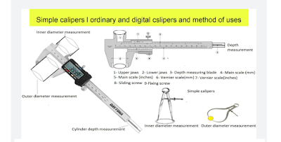
Simple calipers and vernier calipers, method of uses and calculations
Calipers: The calipers are very useful instruments. These instruments are used to measure the diameter of the cylinder, bore, bearing size, ...
-
 If you are searching for genuine hand woven, sustainable, and eco – friendly warm shawls, stoles, and scarves, the Himalayan weavers is off...
 -
 please click on the below link to read this article in Hindi यार्न की परिभाषा और यार्न के विभिन्न प्रकार या यार्न का वर्गीकरण VARIOUS TYPE...
 -
 CARDING: The carding is the second process of spinning which converts fed material (lap) into the uniform strand of fibres called “...
 -
 please click on the below link to read this article in Hindi एक सिस्टम से दूसरे सिस्टम में यार्न काउंट का रूपांतरण CONVERSION OF YARN COUN...